Токарные инструменты Iscar (часть 1) 2026 - страница 402
Навигация
 Каталог Iscar монолитные фрезы 2022
 Руководство Iscar режущий инструмент в производстве штампов и пресс-форм
 Каталог Iscar токарный инструмент 2017
 Каталог Iscar новые продукты 2018
 Каталог Iscar державки и пластины для нарезания резьбы 2022
 Каталог Iscar сверла ружейные и для глубокого сверления 2022
- TURNING TOOLS AND INSERTS
- GROOVE-TURN
- TOOLS FOR MINIATURE PARTS
- BROACHING TOOLS
- PARTING
- FACE GROOVING AND TURNING
- TURNING TOOLS
- Tool Identification System
- External Tools
- Jet High-Pressure Tools
- Tools for Ceramic Inserts
- Boring Bars
- TURNING INSERTS
- Insert Identification System
- Selection Guide for Chipformers and Grades
- Negative Inserts
- Positive Inserts
- Inserts for Machining Aluminum
- Pipe Skiving Inserts
- TURNING userguide
- Cutting Speed Recommendations
- Turning Grades Chart
- GROOVE-TURN
- Selection Guide
- External Tools and Inserts
- HELI-GRIP Tools and Inserts
- TOP-GRIP Tools and Inserts
- CUT-GRIP Tools and Inserts
- Tools, Adapters and Blades (short pocket)
- Tools, Adapters and Blades (long pocket)
- Utility Inserts
- Precision Ground Inserts
- Inserts for Specific Applications and Materials
- Cast Iron
- Hardened Steel
- High Temperature Alloys
- Aluminum
- Next to Shoulder
- Undercutting
- Pulley V Grooves
- T/L Grooves
- GDMW Tools and Inserts
- Multi-Corner Grooving Tools and Inserts
- PENTACUT (5 cutting edges)
- GTGA (3 cutting edges)
- GROOVE-4-CUT (4 cutting edges)
- Tools and Inserts for Heavy Duty Grooving and Turning
- DOVE-IQ-GRIP Tools and Inserts
- SUMO-GRIP Tools and Inserts
- CUT-GRIP Tools and Inserts
- PENTA-CUT Tools and Inserts
- Internal Tools and Inserts
- QUICK-I-GROOVE Boring Bars Dmin 16.5 mm (GQIN inserts)
- CUT-GRIP Boring Bars Dmin 12.5 mm (GEPI Inserts)
- CUT-GRIP Boring Bars Dmin 20 mm (GIPI/GIFI/GINI Inserts)
- TOP-GRIP Boring Bars Dmin 20.5 mm
- HELI-GRIP Boring Bars Dmin 26 mm
- CUT-GRIP Boring Bars Dmin 64 mm (GDMY/F/N 8 mm Inserts)
- CUT-GRIP Blades Dmin 70 mm
- Form Tools
- Tools for Miniature Parts
- USER GUIDE
- Broaching Tools
- Tools for Aluminum Wheels
- PARTING
- FACE GROOVING AND TURNING
- TOOL BLOCKS
- EXCHANGEABLE HEAD HOLDERS
- External Tools and Inserts
- QUICK-2-CUT
- SWISS-CUT
- QUICK-SWISS
- CUT-GRIP
- SWISS-GRIP
- PENTA-CUT
- PICCO LINES
- ACE-CUT
- PICCO-ACE
- PASS-CUT
- QUICK-SWISS
- PICCO-3-CUT (Dmin 3 mm)
- PICCO-JET (Dmin 0.8 mm)
- PICCO-INDEX (Dmin 4.5 mm)
- Internal Boring Bars and Inserts
- MINI-CHAM (Dmin 4 mm)
- MINCUT (Dmin 8 mm)
- CHAM-GROOVE (Dmin 8 mm)
- Full range of PENTA-CUT Tools & Inserts
- Selection Guide
- Tools and Inserts
- DO-GRIP
- TANG-GRIP
- LOGIQ-F-GRIP
- DO-F-GRIP
- JET-CROWN
- SELF-5-GRIP
- TANG-5-GRIP
- CUT-GRIP
- PENTA-IQ-GRIP
- PENTA-CUT R/L Parting Inserts
- User Guide
- SELECTION GUIDE
- FACE GROOVING TOOLS FOR MINIATURE PARTS
- PICCO-CUT
- CHAM-GROOVE
- MINCUT
- TOOLS AND INSERTS
- HELI-FACE
- CUT-GRIP
- TANG-GRIP
- SELF-GRIP
- PENTA-CUT
- User Guide
- Cutting Speed Recommendations
- Face Grooving Grades Chart
- CAMFIX (ISO 26623-1)
- HSK-T (ISO 12164-3 T Type and ICTM Standard)
- IM (ISO 26622-1 and Mazak XMZ Standard)
- AD-CCLNX
- AD-CRSNX
- ADMP D22
- ADMP D45
- AD-SET
- A/E-SCLXR/L-06X
- A/E-SDXNR/L-07
- A/E-SDZNR/L-07
- A/E-SEXPR/L-03
- A/E/S-SCLCR/L
- A/E/S-SDUCR/L
- A/E/S-STFPR/L
- A/E-STFPR-X
- A/E-SWLNR/L-04
- A/E-SWUCR
- Anti-Vibration Blades
- A-PCLXR/L
- A-PSKNR/L-09
- A-PTFNR/L-X/G
- A-PWLNR/L-X/G
- A-SDUCR/L-13-SL
- A/S-MWLNR/L-W
- A/S-PCLNR/L
- A/S-PCLNR/L-X/G
- A/S-PDUNR/L
- A/S-PWLNR/L
- A/S-STLPR/L
- A/S-SVLBCR/L
- A/S-SVLBCR/L
- A/S-SVLFCR/L; A-SVUCR/L
- A/S-SVQCR/L
- A-SVLFNR-AL-JHP
- A-SVQNR/L-AL-JHP
- A-SVUNR/L
- A-SXFOR-DR
- A-SXFOR/L
- AVC-D80-VH
- AVC-DDMNR/L
- AVC-DDUNR/L
- AVC-DDUNR/L-VH
- AVC-DVUNR/L
- AVC-GAIC
- AVC-GAIR/L
- AVC-GEAIR/L
- AVC-PCLNR/L
- AVC-PCLXR/L
- AVC-PTLNR/L
- AVC-PXJNR/L
- AVC-SCLCR/L
- AVC-SCLXR/L-06X
- AVC-SDJCN-Y
- AVC-SDUCR/L
- AVC-SDUCR/L-VH
- AVC-SET
- AVC-SET-LEV
- AVC-SRDCN-Y
- AVC-SVLCR/L
- AVC-SVLCR/L-VH
- AVC-SVMCR/L
- AVC-SVPCR/L
- AVC-SVQCR/L
- AVC-SVUCR/L
- AV-D
- AV-D-VH
- BGM N-J
- BGM R/L-J
- BGTR/L-B-JHP
- BHDN
- BLKT AV-JHP
- CAMFIX ISO 26623-1
- CAMFIX - ISO 26623-1 Standard Quick Change Shanks
- C#-AV-C
- C#-AV-C-VH
- CC95MT-SM
- CCET-WF
- CCGT-AF
- CCGT-AS
- CCGT-F1M-12P
- CCGT-F1M-20P
- CCGT-F1P
- CCMT-14
- CCMT/CCGT
- CCMT/CCGT-SM
- CCMT-CERMET
- CCMT-F3M
- CCMT-F3P
- CCMT-F3PW
- CCMT-M3M
- CCMT-M3P
- CCMT-PF
- CCMT-WG
- C# CXXNR/L-AD-JHP
- C#-DDJNR/L
- C#-DTGNR/L
- CGFG 51-P8
- C#-GHAD-8
- C#-GHAD-JHP
- C#-GHAIR/L
- C#-GHAPR/L-8
- C#-GHDR/L
- C#-GHIC
- CGHN-8-10D
- CGHN 26-M
- CGHN 32-DGM
- CGHN 32-M
- CGHN-D
- CGHN-DG
- CGHN-P8
- CGHN-S
- CGHR/L-12-14D
- CGHR/L-P8DG
- CGIN 26
- CGPAD
- CGPAD-JHP
- C#-HAD
- C#-HAPR/L
- C#-HATA
- C#-HELIR/L
- C#-HFIR/L-MC
- CKJNR/L
- CKNNR/L
- C#-MAHD
- C#-MAHD-JHP
- C#-MAHDR-45
- C#-MAHPD
- C#-MAHPD-JHP
- C#-MULNR/L-MW
- CNGG-F3N
- CNGX-M3N
- CNMA
- CNMG-CERMET
- CNMG/CNGG-PP
- CNMG/CNGG-SF
- CNMG/CNGG-TF
- CNMG-F3M
- CNMG-F3P
- CNMG-F3S
- CNMG-GN
- CNMG-M3M
- CNMG-M3P
- CNMG-MR
- CNMG-NF
- CNMG-NR
- CNMG-R3M
- CNMG-R3P
- CNMG-VL
- CNMG-WF
- CNMG-WG/NRW
- CNMM-H3P
- CNMM-H4P
- CNMM-H5P
- CNMM-M4PW
- CNMM-NR
- CNMM-R3P
- CNMS-12
- CNMX-M3/4MW
- CNMX-M3/4PW
- COMG-R3P-IQ
- COMM-R3P-IQ
- C#-PCLNR/L-12-JHP
- C#-PCLNR/L-X
- C#-PCLNR/L-X-JHP
- C#-PCLOR/L-IQ
- C#-PDJNR/L-JHP
- CPGT-SM
- CPMT-PF
- C#-PWLNR/L-08-JHP
- C#-PWLNR/L-X
- C#-PWLNR/L-X-JHP
- C#-PWLOR/L-IQ
- C#-Q3-SMXCN-SL-Y
- C#-Q3-SMXCR/L-SL
- C#-Q6-DMXNN-SL-Y
- CR HFIR-M
- CROWN (ECD)
- CR THDN-IQ
- C#-SCLCR/L-JHP
- C#-SDJCN-13-Y
- C#-SDJCR-JHP
- C#-SDJCR/L
- C#-SDJCR/L-13-SL-JHP
- C#-SDNCN
- C#-SDNCN-13-SL-JHP
- CSDPN
- C#-SH-E-JHP
- C#-SH-JHP
- C#-SLANR/L-TANG
- C#-SRDCN-16-Y
- C#-SRGCR-12-JHP
- C#-SRGCR/L
- CSSPR/L
- C#-SVJCR/L
- C#-SVJCR/L-JHP
- C#-SVJNR/L-F
- C#-SVVCN
- C#-TBK-R/L
- C#-TBU
- CTFPR/L
- CTGPR/L
- CXGG-M3N-P
- CXMG-F3M
- CXMG-F3P
- CXMG-M3M
- CXMG-M3P
- CXMU-F3M
- CXMU-F3P
- D6NMG-F3P
- D6NMG-M3M
- D6NMG-M3P
- DCBNR/L
- DCET-WF
- DCGT-AF
- DCGT-AS
- DCGT-F1M-12P
- DCGT-F1M-20P
- DCLNR/L
- DCLNR/L-JHP-MC
- DCMT-14
- DCMT-CERMET
- DCMT/DCGT
- DCMT/DCGT-PF
- DCMT/DCGT-SM
- DCMT-F3P
- DCMT-F3P-SL
- DCMT-M3M
- DCMT-M3M-SL
- DCMT-M3P
- DCMT-PF-SL
- DCMT-SM-SL
- DDJNR/L
- DDJNR/L-JHP-MC
- DGAD-B-D
- DGAD/HGAD
- DGAQ
- DGAQ-JHP
- DGFH
- DGFH-JHP
- DGFHL-26B-TR-D
- DGFHR/L
- DGFHR/L-BC-JHP
- DGFHR/L-B-D..(R/L)
- DGFS
- DGHAL-DECO
- DGN-B
- DGN-C-XL
- DGN/DGNC/DGNM-C
- DGN/DGNM-J/JS/JT
- DGN-J/JS-D
- DGN-J-XL
- DGN-LF/LFT
- DGN-MF
- DGN-P
- DGN-T
- DGN-UT/UA
- DGN-W
- DGN-WP
- DGN-Z
- DGPAD-D12/22-JHP
- DGPAD-JHP
- DGPAD-XL-JHP
- DGR/L-B
- DGR/L-C DGRC/LC-C
- DGR/L-C-XL
- DGR/L-J/JS
- DGR/L-J/JS-D
- DGR/L-J-XL
- DGR-P
- DGR-WP
- DGR-Z/ZS
- DGTR/L
- DGTR/L-B/BC-D
- DGTR/L-BC-T
- DGTR/L-B-D-JHP-SL
- DGTR/L-B-D-JHP-SL-MC
- DGTR/L-B-D-SH
- DGTR/L-B-D-SH (NARROW CUT)
- DGTR/L-B-D-TR
- DGTR/L-B-T-SH
- DGTR/L-XL
- D/HGAD RE/LE-JHP
- DNGG-M3N
- DNGP-F2M
- DNGP-F2P
- DNMA
- DNMG-CERMET
- DNMG/DNGG-PP
- DNMG/DNGG-SF
- DNMG/DNGG-TF
- DNMG-F3M
- DNMG-F3P
- DNMG-F3S
- DNMG-GN
- DNMG-M3M
- DNMG-M3P
- DNMG-NF
- DNMG-NR
- DNMG-PF
- DNMG-VL
- DNMG-WG
- DNMM-NM
- DNMM-R3P
- DNMS-12
- DNMX-M3P
- DSBNR/L
- DSDNN
- DSKNR/L
- DSSNR/L
- DTF50 FSHDR-8
- DTF50 FSHIUR
- DTF50 SVXCR-16X2
- DTF50 SVXCR-22
- DTGNR/L
- DWLNR/L
- DWLNR/L-JHP-MC
- DXJNR/L-X-JHP-MC
- E-GEHIR / E-GHIR
- EPGT-F1P
- E-PWLNR/L-HEAD
- E-SCLCR/L-HEAD
- E-SDUCR/L-HEAD
- E/S-SWUBR/L
- E-STFCR-HEAD
- E-STFPR-HEAD
- EX C# (CAMFIX extension)
- FGHDUR
- FGPAM
- FSHDR
- FSHIUR
- FSPA/FSMA
- FTB
- FTHN
- GADR/L-8
- GADR/L-JHP
- GAFG-R/L-8
- GAIR/L
- GDK
- GDMA
- GDMF
- GDMM-CC
- GDMN
- GDMT
- GDMU
- GDMW 2.4
- GDMY
- GDMY-F
- GDMY (full radius)
- GDP
- GDPY
- GEAIR/L
- GEHIMR/L
- GEHIMR/L-SC
- GEHIR/L
- GEHIR/L-SC
- GEHIUR/L
- GEHSR
- GEHSR/L-SL
- GEMI
- GEMI (full radius)
- GEPI
- GEPI (full radius)
- GEPI-RX/LX
- GEPI-UN/UR/UL
- GEPI (W
- GFF-N
- GFF-R/L
- GFHR/L-JHP
- GFQR
- GFT-C
- GFT-J
- GHAIR/L-GE
- GHAIR/L-GI
- GHAIR/L-SC-GE
- GHAPR/L-8
- GHAR/L-8
- GHAR/L-JHP
- GHDKR/L
- GHDR/L-8A
- GHDR/L-JHP (long pocket)
- GHDR/L-JHP-MC (short pocket)
- GHDR/L-JHP (short pocket)
- GHDR/L (long pocket)
- GHDR/L/N 12/14
- GHDR/L (short pocket)
- GHFG-R/L-8
- GHFGR/L-8
- GHGR/L
- GHIC-50
- GHIC-70
- GHIC-85
- GHIFR/L-A
- GHIR/L-C (W=4-6.4)
- GHIR/L-SC (W=2-4.8)
- GHIR/L (W=1.9-6.4)
- GHIR/L (W=7.0-8.3)
- GHIUR/L
- GHIUR/L-C-22.5A-8V
- GHIUR/L-C-A (15° & 27.5°) Bars
- GHIUR/L-UC
- GHMPR/L
- GHMR/L
- GHMUR/L
- GHSR/L
- GHSR/L-JHP-SL
- GHVR/L
- GIA-K (long pocket)
- GIA-K (W=3-6)
- GIF
- GIF-E (W=4-6)
- GIF-E (W=4-6 full radius)
- GIF-E (W=8,10)
- GIF-E (W=8,10 full radius)
- GIF (full radius)
- GIFG-E (W=8)
- GIFI
- GIFI-E
- GIFI-E (full radius)
- GIF (long pocket)
- GIG
- GIM-C
- GIMF
- GIMIY
- GIM-J
- GIM-J-RA/LA
- GIMM 8CC
- GIMN
- GIMT
- GIM-UT
- GIM-UT-RA/LA
- GIM-W
- GIM-W-RA/LA
- GIMY
- GIMY 1260
- GIMY-F
- GIMY (full radius)
- GIMY-UN
- GINI-E
- GIP
- GIPA 8-35V (V-shape)
- GIPA (full radius W=3-6)
- GIPA/GIDA 8 (full radius)
- GIPA (W=3-6)
- GIP-E
- GIP-E (full radius)
- GIP (flat top CW
- GIP (full radius)
- GIP (full radius CW
- GIPI
- GIPI (CW
- GIPI-E
- GIPI (full radius)
- GIPI (full radius CW
- GIPI-RX/LX
- GIPI-UR/UL
- GIPM-A46 / GIP-1250
- GIP-RX/LX
- GIP-UN
- GIPY
- GIQR/L 8
- GIQR/L 8-R
- GIQR/L 11
- GIQR/L 11-15
- GIQR/L 11-15-R
- GIQR/L 11-R
- GIQR/L-A18
- GIQR/L-B18
- GIQR/L-MT
- GIQR/L-WT
- GITM
- GITM (full radius)
- GIVR/L
- GPV
- GQHINR/L
- GQIN
- GRIP
- GRIPA
- GRIPA (full radius)
- GRIP (full radius)
- GRIP-T
- GTGA
- GTMA
- HAI-C
- HAPR/L
- HAR/L
- HELIIR/L
- HELIR/L
- HFAER/L-4
- HFAER/L-5T, 6T
- HFAIR/L-4
- HFAIR/L-DG
- HFFA
- HFFH
- HFFR/L-T
- HFHPR/L-M
- HFHR/L-3T
- HFHR/L-4T
- HFHR/L-5T
- HFHR/L-6T
- HFHR/L-M
- HFIR/L-MC
- HFPAD-3
- HFPAD-4
- HFPAD-5
- HFPAD-6
- HFPAD-JHP
- HFPN
- HFPR/L
- HFPR/L (full radius)
- HGAER/L-3
- HGAIR/L-3
- HGFH
- HGHR/L-3
- HGN-C
- HGN-J
- HGN-UT
- HGPAD
- HGPAD-JHP
- HGPL
- HGR/L-C
- HGR/L-J/JS
- HLPGR/L
- HMSN-New Britain
- HSK 63 HATA
- HSK A63WH-DDJNR/L
- HSK A63WH-DDNNN
- HSK A63WH-MAHDOR
- HSK A63WH-MAHDR-45
- HSK A63WH-MAHUR/L
- HSK A63WH-MULNR-J12MWX2
- HSK A63WH-MULNR/L-MW
- HSK A63WH-MUMNN-MW
- HSK A63WH-SDJCN-13-Y
- HSK A63WH-SRDCN-Y
- HSK A63WH-SVJCR/L
- HSK A63WH-SVVNN-F
- HSK A-WH-TBK-R/L
- IH-HFAIR
- IH-HFPAD
- IHSR-MIFR
- IH-TNFPAD
- IM-GHAD-8
- IM-HAD
- IM-HAPR/L
- IM-HFIR-MC
- IM-MAHD
- IM-MAHPD
- IM-TBU
- JHP CONNECTOR
- JHP COPPER SEAL
- JHP ELBOW
- JHP HOSE
- JHP NIPPLE
- JHP QC CONNECTOR
- JHP QC ELBOW
- JHP QC HOSE
- JHP QC KIT
- KIT PICCO Face
- KIT PICCO SET
- KNMX
- KNUX
- LNMX 19/30
- LNMX-HF
- LNMX-HM
- LNMX-HT
- LNMX-WG
- LOMX-H6P
- LPGIR/L
- MAHPR/L
- MAHPR/L-JHP
- MAHPR/L-XL-JHP
- MAHR/L
- MAHR/L-JHP
- MAHR/L-JHP-MC
- MAHR/L-MG-XL-JHP
- MAHR/L-MG-XL-JHP-MC
- MCLNR/L
- MEFL
- MFHR-JHP
- MG
- MGCH
- MGCH-C (face)
- MGSIR/L
- MG STFPR-X
- MG-SWUBR/L
- MG-SWUCR
- MGUHR
- MIFHR
- MIFR
- MIGR 8
- MINCUT KIT
- MIUR 8
- MTENN-W
- MTJNR/L-W
- MULNR/L-12MW
- MVJNR/L
- MVVNN
- MWLNR/L-13W
- MWLNR/L-W
- NMAHR/L-JHP
- NQCH-DGTR/L-D22-SH-JHP
- NQCH FIXTURE
- NQCH-GHSR/L-JHP
- NQCH-JHP
- NQCH-PCHR/L-24-JHP
- NQCH-PCHR/L-S-JHP
- NQCH-PCLXR/L-S-JHP
- NQCH-PTJNR/L-S-JHP
- NQCH-SCACR/L-S-JHP
- NQCH-SCHR/L-BF-JHP
- NQCH-SCLXR/L-JHP
- NQCH-SDACR/L-S-JHP
- NQCH-SDJCR/L-S-JHP
- NQCH-SDJNR/L-S-JHP
- NQCH-SDNCN-S-JHP
- NQCH-SVACR/L-S-JHP
- NQCH-SVJCR/L-S-JHP
- NQCH-SVVCN-S-JHP
- NQCH-SWLNR/L-S-JHP
- NQCH-TGVR/L-JHP
- NQCH-Y-SCHR-BF-JHP
- NQCH-Y-SDJCR-S-JHP
- NQCH-Y-SVJCR-S-JHP
- PADR/L
- PCAD RE/LE-JHP
- PCADR/L
- PCADR/L 34N-RE
- PCADR/L-JHP
- PCADRS/LS-JHP
- PCBNR/L
- PCBOR/L-IQ
- PCHBR/L
- PCHPR/L
- PCHPRS/LS
- PCHR/L-24
- PCHR/L-24-JHP
- PCHR/L-24-JHP-MC
- PCHR/L-24-JHP-QC/MC
- PCHR/L-27-JHP-MC
- PCHR/L-34
- PCHR/L-34-JHP
- PCHR/L-34-JHP-MC
- PCHR/L-D-IQ
- PCHR/L-D-JHP
- PCHRS-24 JHP-QC/MC
- PCHRS/LS
- PCHRS/LS-17
- PCHRS/LS-17-JHP
- PCLCR/L-S
- PCLCR/L-S-JHP
- PCLCR/L-S-JHP-MC
- PCLNR/L
- PCLNR/L-12-JHP
- PCLNR/L-PAD-JHP
- PCLNR/L-X
- PCLNR/L-X-JHP
- PCLNR/L-X-JHP-MC
- PCLOR/L-IQ
- PCLXR/L
- PCLXR/L-JHP
- PCLXR/L-JHP-MC
- PCLXR/L-S
- PCLXR/L-S-JHP
- PDACR/L-S
- PDACR/L-S-JHP
- PDACR/L-S-JHP-MC
- PDJNR/L
- PDJNR/L-JHP
- PDJNR/L-JHP-MC
- PDJNR/L-PAD-JHP
- PDJNR/L-S
- PENTA 17-ER/EL
- PENTA 17-MT-RS/LS
- PENTA 17-NP-RS/LS
- PENTA 17-NX-RS
- PENTA 17-P-RS/LS
- PENTA 17-P-RS/LS (full radius)
- PENTA 17R/L-P-RS
- PENTA 17R/L-SP-RS
- PENTA 17-WT-RS/LS
- PENTA 24N-C
- PENTA 24N-C (full radius)
- PENTA 24N-C-SL
- PENTA 24N-J
- PENTA 24N-J (full radius)
- PENTA 24N-J-RS
- PENTA 24N-J-SL
- PENTA 24N-NF-RS-SL
- PENTA 24N-NF-RSSL (full radius)
- PENTA 24N-PF (full radius)
- PENTA 24N-PF/P
- PENTA 24N-PF-RS
- PENTA 24N-RS/LS
- PENTA 24N-Z
- PENTA 24R-C
- PENTA 24R/L-DSL
- PENTA 24R/L-J
- PENTA 24R/L-Z
- PENTA 24R-P
- PENTA 34F-R/L
- PENTA 34F-RS/LS
- PENTA 34N-C
- PENTA 34N-J
- PENTA 34N-PB
- PENTA 34R/L-C
- PENTA 34R/L-J
- PENTA 34R/L-PB
- PENTA D-N-C
- PENTA D-N-J
- PENTA D-N-PB
- PENTA D-R/L-C
- PENTA D-R/L-J
- PENTA D-R/L-PB
- PENTAS 27 blanks
- PHAR/L
- PHGR/L
- PHSR/L
- PICCO-010/610(Face Grooving)
- PICCO-010(Round Face Groove)
- PICCO-015 (Face Grooving)
- PICCO-016/020(Face Grooving)
- PICCO-55°-Thread
- PICCO-620(Groove Along Shaft)
- PICCO ACE
- PICCO ACE-BH
- PICCO ISO Full Profile
- PICCO ISO Full Profile Fine
- PICCO/MG PCO (Holder)
- PICCO R 050.20
- PICCO R/L 002-007
- PICCO R/L 004-007 (Radius)
- PICCO R/L 047
- PICCO R/L 050, 053, 055
- PICCO R/L 050-C
- PICCO R/L 060
- PICCO R/L-60°-Thread
- PICCO R/L 070
- PICCO R/L 080
- PICCO R/L 090
- PICCO R/L 520
- PICCO R/LHD 050
- PICCO R/LM
- PICCO R/LX050
- PICIN-A-SCLCR/L
- PICIN-A-SIR/L
- PICIN-A-SWUBR/L
- PICIN-MGSIR/L
- PICIN-SCLCR/L
- PICIN-SWUBR/L
- PICJ RF-D8-T(Face Grooving)
- PICJ RF-D16/20-T(Face Grooving)
- PICJ RF-T-20(Grooving Along Shaft)
- PICJ RF-T(Round Face Grooving)
- PICJ R/LBC
- PICJ R/LBT
- PICJ R/LCH
- PICJ R/LF-D6/8-T(Face Grooving)
- PICJ R/LG
- PICJ R/LP
- PICJ R/LT20
- PICJ R/LT20-C
- PICJ R/LT20-H
- PICJ R/LT45
- PICJ R/LT47
- PICJ R/LT90
- PICJ R/LT2020
- PICJ R/LTH (60° Threading)
- PICJ RTH (55° Threading)
- PLANR/L-TANG
- PLBOR/L
- PMC R/L
- PQFNR/L
- PQLCR/L
- PQLCR/L-S
- PQLNR/L
- PQSNR/L
- PRDCN
- PRGCR
- PRWR/L
- PRWR/L 175-CA
- PRWR/L 177-CA
- PSANR/L
- PSBNR/L
- PSBNR/L-JHP-MC
- PSBOR/L-IQ
- PSDNN
- PSDNN-JHP
- PSDON-IQ
- PSKNR/L
- PSSNR/L
- PSSNR/L-JHP
- PSSNR/L-JHP-MC
- PTFNR/L
- PTGNR/L
- PTGNR/L-X
- PTGNR/L-X-JHP
- PTGNR/L-X-JHP-MC
- PVACR/L-S
- PVACR/L-S-JHP
- PVACR/L-S-JHP-MC
- PWLNR/L
- PWLNR/L-08-JHP
- PWLNR/L-S
- PWLNR/L-X
- PWLNR/L-X-JHP
- PWLNR/L-X-JHP-MC
- PWLOR/L-IQ
- PWXOR/L-TF-IQ
- Q3-MCMT-R3M-SL
- Q3-MCMT-R3P-SL
- Q3-SMXCN-SL-JHP
- Q3-SMXCR/L-SL-JHP
- Q6-DMXNN-SL-JHP
- Q6-DMXNR/L-SL-JHP
- Q6-MNMG-M3M-SL
- Q6-MNMG-M3P-SL
- QCMT-PF
- QCMT-SM
- QGI 30N-P
- QGI 30N-PF
- QNMG-GN
- QNMG-NF
- QNMG-PP
- QNMG-TF
- QTHR/L-30-JHP-MC
- RCMT-14
- RCMT-M3P
- RCMT-SR
- RCMX
- RCMX-M3P-R
- RCMX-NR
- RCMX-R3P-R
- RE-C#
- RNMG
- S/A-SQLCR/L
- S/A-SVJCR/L
- SBB
- SBTB-JHP-T/R
- SBTH-ER
- SBTH-JHP
- SBTH-PICCO
- SBTS##S-JHP
- SBTT#-16ER/L-JHP
- SBTT/L/A-SDJNR/L07-JHP
- SBTT#-MIFHR-JHP
- SBTT#-PCHRS/LS-17-JHP
- SBTT-PCLXR/L09-JHP
- SBTT#-SCHR/L22-JHP
- SBTT#-SCLCR/L-JHP
- SBTT#-SDJCR/L-JHP
- SBTT-SDNCN-JHP
- SBTT#-SVJBR/L-JHP
- SBTT#-SVJCR/L-JHP
- SBTT#-SVQCR/L-JHP
- SBTT#-SVUCR/L-JHP
- SBTT-SVVCN-JHP
- SC45MT-SM
- SCACR/L-S
- SCB
- SCB (light fit)
- SCGT-AS
- SCHR/L-22BF
- SCHR/L-22BF-JHP
- SCHR/L-41BF
- SCIR/L-22-AD
- SCIR/L-22-AR/AL
- SCIR/L-22-BR/BL/BRA/BLA
- SCIR/L-22-ER/EL/ERA/ELA
- SCIR/L-22-NP
- SCIR/L-22-N/R/L
- SCIR/L-22-NX
- SCIR/L-41-AD
- SCIR/L-41-AR/AL
- SCIR/L-41-BRA/BLA
- SCIR/L-41-ERA/ELA
- SCIR/L-41-NP
- SCIR/L-41-N/R/L
- SCLCR/L
- SCLCR/L-PAD-JHP
- SCLCR-PAD
- SCLXR/L 06X
- SCLXR/L 06X-JHP
- SCLXR/L 06XS
- SCLXR/L 06XS-JHP-MC
- SCMT-14
- SCMT-19
- SCMT-F3M
- SCMT-F3P
- SCMT-M3M
- SCMT-M3P
- SCMT-SM
- SC-PICCO
- S-CSKPR
- S-CTFPR/L
- SDACR/L-S
- SDACR/L-S-SL-JHP
- S-DCLNR/L
- S-DDUNR/L
- SDHCR/L-S
- SDJCR/L
- SDJCR/L-13-SL
- SDJCR/L-JHP-MC
- SDJCR/L-PAD-JHP
- SDJCR-PAD
- SDJCR-SL-PAD-JHP
- SDNCN
- SDNCN-13-SL
- S-DWLNR/L
- SGAQ
- SGBHR/L
- SGFFA
- SGFFH
- SGFFR/L
- SGTBF
- SGTBK
- SGTBR/L
- SGTBU/SGTBN
- SH-D
- SH-S#-N-AVC
- SKJNR/L
- SLANR/L-15-TANG-JHP
- SLANR/L-TANG
- SLBNR/L-TANG
- SLFNR/L-TANG
- S-MTLCR/L-W
- S-MTLNR/L-W
- S-MULNR-MW
- SNMA
- SNMG-EM-M/R
- SNMG-F3M
- SNMG-F3P
- SNMG-F3S
- SNMG-GN
- SNMG-M3M
- SNMG-M3P
- SNMG-NR
- SNMG-PP
- SNMG-R3M
- SNMG-R3P
- SNMG-TF
- SNMG-VL
- SNMM-H3P
- SNMM-H4P
- SNMM-H5P
- SNMM-NM
- SNMM-NR
- SNMM-R3P
- SNMM-R4P
- SNMX 150608R-..
- SNMX 150708R-..
- SOMG-R3P-IQ
- S-PLANR-TANG
- SPMR
- S-PQFNR/L
- S-PQLNR/L
- S-PTFNR/L
- SRDCN
- SRGCR-12-JHP
- SRGCR/L
- SSBCR/L
- S-SLANR/L-TANG
- SSSCR/L
- S-STFCR/L
- S-STLCR/L
- S-SUXCR/L-CM
- STFCR/L
- STGCR/L
- SUXCR/L-CM
- SVACR/L-S
- SVANR/L-FS
- SVHNR/L-AL-JHP
- SVJCR/L
- SVJCR/L-16-JHP
- SVJCR/L-PAD-JHP
- SVJCR-PAD
- SVJNR/L-F
- SVPCR/L-S
- SVVCN
- SVVNN-AL-JHP
- SVVNN-F
- SVXCR/L
- SVXCR/L
- SWAPR/L-S
- SWAPR-PAD
- SWDPR/L
- SXCIB
- SXCIR
- SXCNN
- TAGB/TAGBA
- TAG N-A
- TAG N-C (full radius)
- TAG N-C/W/M
- TAG N-HF
- TAG N-J/JS/JT
- TAG N-LF
- TAG N-MF
- TAG N-T
- TAG N-UT
- TAGPAD-JHP
- TAGPAD-XL-JHP
- TAGPAD-Y-JHP
- TAG R/L-C
- TAG R/L-J/JS
- TCGT-AS
- TCMT-F3P
- TCMT-M3M
- TCMT-M3P
- TCMT-PF
- TCMT-SM
- TGAD
- TGAD RE/LE-JHP
- TGAQ
- TGAQ-ECD (JET-CROWN)
- TGAQ-JHP
- TGBHR/L
- TGBHR/L-JHP
- TGDR/L
- TGFH-JHP
- TGFHL-TR
- TGFH-MB
- TGFH/R/L
- TGFHR/L
- TGFHR/L-JHP
- TGFH-S
- TGFS
- TGHN 26-M
- TGHN-D
- TGHN-S
- TGIR/L-C
- TGMA
- TGMF (full radius)
- TGMF/P
- TGPAD
- TGPAD-JHP
- TGSU
- TGTBQ-ECD-JHP (JET-CROWN)
- TGTBQ-JHP
- TGTBQ-JHP-ECD-MC
- TGTBQ-JHP-MC
- TGTBQ-JHP-RIB
- TGTBU
- TGTBU-JHP
- TGTBY-JHP
- TGTR/L-2T..SH-L120
- TGTR/L-D
- TGTR/L-IQ
- TGTR/L-IQ-2Z
- TGTR/L-JHP
- TGTR/L-JHP-MC
- TGV N
- TGV R/L
- TGVR/L-JHP
- THBR/L/N-IQ
- THDR/L-IQ
- THDR/L/N
- THMPR/L D22-JHP
- THMPR/L D45-JHP
- THQR/L
- TIGER
- TIGER-IQ
- TIGERV
- TNFFA-IQ
- TNFFH-IQ
- TNF GN-IQ
- TNF-M-IQ
- TNFPAD-XL-JHP
- TNF-P-IQ
- TNGG-M3N
- TNMA
- TNMG-F3M
- TNMG-F3P
- TNMG-F3S
- TNMG-FFG-CERMET
- TNMG-GN
- TNMG-M3M
- TNMG-M3P
- TNMG-NF
- TNMG-PF
- TNMG-SF
- TNMG-TF
- TNMG/TNGG-PP
- TNMG-VL
- TNMM-NR
- TNMS-12
- TNMX-M3/4MW
- TNMX-M3/4PW
- TPGB
- TPGB-XL
- TPGH-R/L
- TPGH-XL
- TPGT-SP
- TPGX
- TPMR
- TPMR-FTF
- TPMR-PF
- TPMT
- TPMT-PF
- UBHCR/L
- UMGR
- UMGR-A55
- UMGR-A60
- VCET-WF
- VCGT-AF
- VCGT-AS
- VCGT-DW (PCD)
- VCGT-F1M-12P
- VCGT-F1M-20P
- VCGT-MD/PF
- VCMT-14
- VCMT-F3M
- VCMT-F3P
- VCMT-FPC-CERMET
- VCMT-M3M
- VCMT-M3P
- VCMT-SM
- VCMW
- VDI-DTF50
- VDI-DTF50E-L60R
- VNGG-M3N
- VNGU-R3N
- VNGU-R3N
- VNMG-F3M
- VNMG-F3P
- VNMG-F3S
- VNMG-FNF-CERMET
- VNMG-M3M
- VNMG-SF
- VNMG-TF
- VNMG/VNGG-NF
- VNMM-PP
- VNMS-12
- V## SQ#-#-D82-JHP
- WBGT
- WBMT
- WCGT
- WNGG-F3N
- WNGP-F2M
- WNGP-F2P
- WNMA/WNMA-WG
- WNMG-CERMET
- WNMG-F3M
- WNMG-F3P
- WNMG-F3S
- WNMG-GN
- WNMG-M3M
- WNMG-M3P
- WNMG-NF
- WNMG-NR
- WNMG-PP
- WNMG-SF
- WNMG-TF
- WNMG-TNM
- WNMG-VL
- WNMG-WF
- WNMG-WG
- WNMM-NM
- WNMX-M3/4MW
- WNMX-M3/4PW
- WOMG-10-T3P-IQ
- WOMG-13-R3P-IQ
- WPEX
- XNMG-F3M
- XNMG-F3P
- XNMG-M3M
- XNMG-M3P
- XNUW
- XNUWB
- XNUWB (tight fit)
- XOMT-DT
- YNMG-F3P
- Y-PCHRS-17
- Y-PCHRS-17-JHP
- Y-SCHR-22BF
- Y-SCHR-22BF-JHP
- Y-SDJCR-S
- Y-SDJCR-S-JHP
- Y-SVJCR-S
- Y-SVJCR-S-JHP
GROOVE-TURN
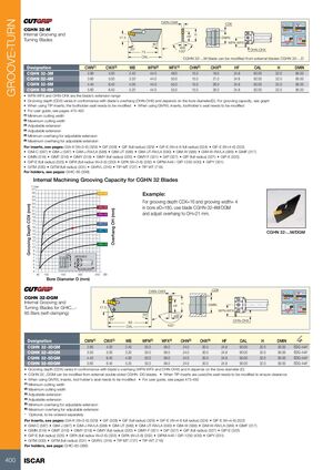
CGHN 32-M
Резцы для внутреннего нарезания канавок и обработки торца
| Обозначение | CWN(1) | CWX(2) | WB | WFN(3) | WFX(4) | OHN(5) | OHX(6) | HF | OAL | H | DMIN |
|---|---|---|---|---|---|---|---|---|---|---|---|
| CGHN 32-3M | 2.80 | 4.00 | 2.40 | 44.0 | 48.0 | 15.0 | 19.0 | 24.8 | 82.00 | 32.0 | 85.00 |
| CGHN 32-4M | 3.60 | 5.00 | 3.20 | 44.0 | 50.0 | 15.0 | 21.0 | 24.8 | 82.00 | 32.0 | 85.00 |
| CGHN 32-5M | 4.40 | 6.40 | 4.00 | 44.0 | 55.0 | 15.0 | 26.0 | 24.8 | 82.00 | 32.0 | 85.00 |
| CGHN 32-6M | 5.60 | 6.40 | 5.20 | 44.0 | 55.0 | 15.0 | 26.0 | 24.8 | 82.00 | 32.0 | 85.00 |
Резец CGHN 32-...M может быть изготовлен из внешних двусторонних резцов CGHN 32-...D
- WFN-WFX и OHN-OHX — диапазон выступа резца
- Глубина нарезания канавки (CDX) изменяется в соответствии с выступом резца (OHN-OHX) и зависит от диаметра отверстия (D). График производительности см. ниже
- При использовании пластин TIP посадочное место державки требует модификации
- При использовании пластин GIVR/L посадочное место державки требует модификации
- Руководство пользователя см. на страницах 475-492
Примечания:
- (1) Минимальная ширина резания
- (2) Максимальная ширина резания
- (3) Регулируемый выступ
- (4) Регулируемый выступ
- (5) Минимальный выступ для регулируемого выступа
- (6) Максимальный выступ для регулируемого выступа
Пластины см. на страницах: GIA-K (W=3-6) (329) • GIF (328) • GIF (полный радиус) (329) • GIF-E (W=4-6 полный радиус) (324) • GIF-E (W=4-6) (322) • GIM-C (587) • GIM-J (587) • GIM-J-RA/LA (588) • GIM-UT (589) • GIM-UT-RA/LA (590) • GIM-W (588) • GIM-W-RA/LA (589) • GIMF (317) • GIMN (319) • GIMT (316) • GIMY (318) • GIMY (полный радиус) (320) • GIMY-F (321) • GIP (327) • GIP (полный радиус) (327) • GIP-E (323) • GIP-E (полный радиус) (325) • GIPA (полный радиус W=3-6) (333) • GIPA (W=3-6) (332) • GIPM-A46 / GIP-1250 (430) • GIPY (331) • GITM (330) • GITM (полный радиус) (331) • GIVR/L (316) • TIP-MT (727) • TIP-WT (718)
Державки см. на страницах: GHIC-85 (398)
Производительность внутреннего нарезания канавок для резцов CGHN 32
Пример: для глубины нарезания канавки CDX=16 и ширины нарезания 4 в отверстии øD=180 используйте резец CGHN-32-4M/DGM и отрегулируйте выступ на OH=21 мм
CGHN 32-DGM
Резцы для внутреннего нарезания канавок и обработки торца для державок GHIC...-85 (самозажимные)
| Обозначение | CWN(1) | CWX(2) | WB | WFN(3) | WFX(4) | OHN(5) | OHX(6) | HF | OAL | H | DMIN |
|---|---|---|---|---|---|---|---|---|---|---|---|
| CGHN 32-3DGM | 2.80 | 4.00 | 2.40 | 53.0 | 59.0 | 24.0 | 30.0 | 24.8 | 90.00 | 32.0 | 93.00 |
| CGHN 32-4DGM | 3.50 | 5.00 | 3.20 | 53.0 | 59.0 | 24.0 | 30.0 | 24.8 | 90.00 | 32.0 | 93.00 |
| CGHN 32-5DGM | 4.40 | 6.40 | 4.00 | 53.0 | 59.0 | 24.0 | 30.0 | 24.8 | 90.00 | 32.0 | 93.00 |
| CGHN 32-6DGM | 5.60 | 6.40 | 5.20 | 53.0 | 59.0 | 24.0 | 30.0 | 24.8 | 90.00 | 32.0 | 93.00 |
- Глубина нарезания канавки (CDX) изменяется в соответствии с выступом резца (WFN-WFX и OHN-OHX) и зависит от диаметра отверстия (D)
- CGHN 32...DGM может быть изготовлен на основе двусторонних внешних резцов CGHN -DG
- При использовании пластин TIP посадочное место требует модификации для обеспечения зазора
- При использовании пластин GIVR/L посадочное место державки требует модификации
- Руководство пользователя см. на страницах 475-492
Примечания:
- (1) Минимальная ширина резания
- (2) Максимальная ширина резания
- (3) Регулируемый выступ
- (4) Регулируемый выступ
- (5) Минимальный выступ для регулируемого выступа
- (6) Максимальный выступ для регулируемого выступа
- * По заказу, поставляется отдельно
Пластины см. на страницах: GIA-K (W=3-6) (329) • GIF (328) • GIF (полный радиус) (329) • GIF-E (W=4-6 полный радиус) (324) • GIF-E (W=4-6) (322) • GIM-C (587) • GIM-J (587) • GIM-J-RA/LA (588) • GIM-UT (589) • GIM-UT-RA/LA (590) • GIM-W (588) • GIM-W-RA/LA (589) • GIMF (317) • GIMN (319) • GIMT (316) • GIMY (318) • GIMY (полный радиус) (320) • GIMY-F (321) • GIP (327) • GIP (полный радиус) (327) • GIP-E (323) • GIP-E (полный радиус) (325) • GIPA (полный радиус W=3-6) (333) • GIPA (W=3-6) (332) • GIPM-A46 / GIP-1250 (430) • GIPY (331) • GITM (330) • GITM (полный радиус) (331) • GIVR/L (316) • TIP-MT (727) • TIP-WT (718)
Державки см. на странице: GHIC-85 (398)