Токарные инструменты Iscar (часть 1) 2026 - страница 393
Навигация
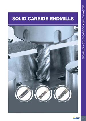 Каталог Iscar монолитные фрезы 2022
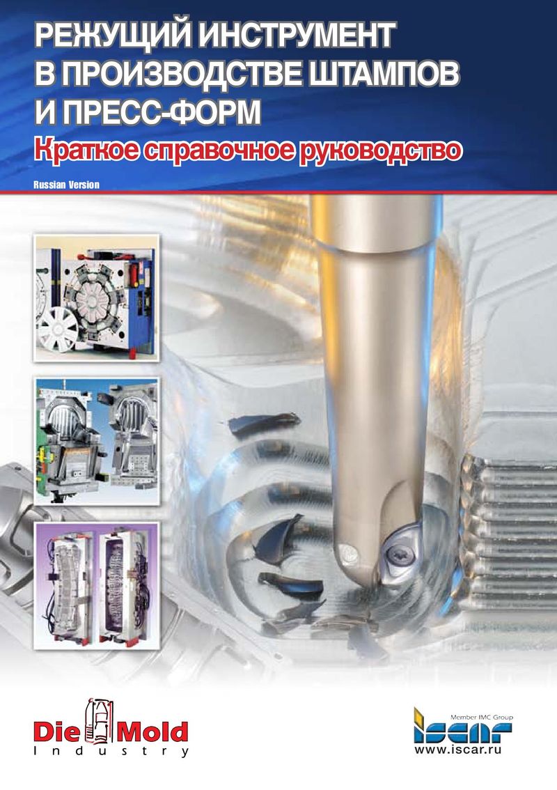 Руководство Iscar режущий инструмент в производстве штампов и пресс-форм
 Каталог Iscar токарный инструмент 2017
 Каталог Iscar новые продукты 2018
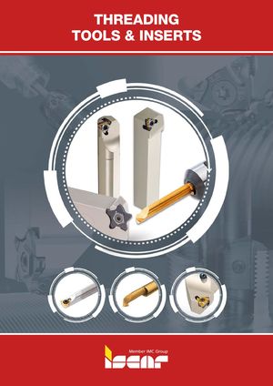 Каталог Iscar державки и пластины для нарезания резьбы 2022
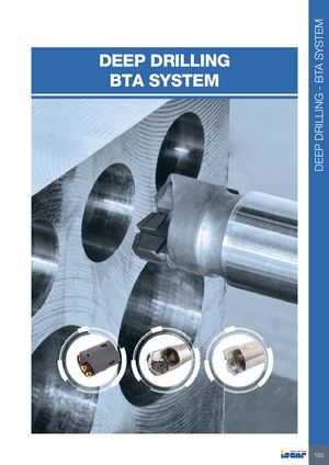 Каталог Iscar сверла ружейные и для глубокого сверления 2022
- TURNING TOOLS AND INSERTS
- GROOVE-TURN
- TOOLS FOR MINIATURE PARTS
- BROACHING TOOLS
- PARTING
- FACE GROOVING AND TURNING
- TURNING TOOLS
- Tool Identification System
- External Tools
- Jet High-Pressure Tools
- Tools for Ceramic Inserts
- Boring Bars
- TURNING INSERTS
- Insert Identification System
- Selection Guide for Chipformers and Grades
- Negative Inserts
- Positive Inserts
- Inserts for Machining Aluminum
- Pipe Skiving Inserts
- TURNING userguide
- Cutting Speed Recommendations
- Turning Grades Chart
- GROOVE-TURN
- Selection Guide
- External Tools and Inserts
- HELI-GRIP Tools and Inserts
- TOP-GRIP Tools and Inserts
- CUT-GRIP Tools and Inserts
- Tools, Adapters and Blades (short pocket)
- Tools, Adapters and Blades (long pocket)
- Utility Inserts
- Precision Ground Inserts
- Inserts for Specific Applications and Materials
- Cast Iron
- Hardened Steel
- High Temperature Alloys
- Aluminum
- Next to Shoulder
- Undercutting
- Pulley V Grooves
- T/L Grooves
- GDMW Tools and Inserts
- Multi-Corner Grooving Tools and Inserts
- PENTACUT (5 cutting edges)
- GTGA (3 cutting edges)
- GROOVE-4-CUT (4 cutting edges)
- Tools and Inserts for Heavy Duty Grooving and Turning
- DOVE-IQ-GRIP Tools and Inserts
- SUMO-GRIP Tools and Inserts
- CUT-GRIP Tools and Inserts
- PENTA-CUT Tools and Inserts
- Internal Tools and Inserts
- QUICK-I-GROOVE Boring Bars Dmin 16.5 mm (GQIN inserts)
- CUT-GRIP Boring Bars Dmin 12.5 mm (GEPI Inserts)
- CUT-GRIP Boring Bars Dmin 20 mm (GIPI/GIFI/GINI Inserts)
- TOP-GRIP Boring Bars Dmin 20.5 mm
- HELI-GRIP Boring Bars Dmin 26 mm
- CUT-GRIP Boring Bars Dmin 64 mm (GDMY/F/N 8 mm Inserts)
- CUT-GRIP Blades Dmin 70 mm
- Form Tools
- Tools for Miniature Parts
- USER GUIDE
- Broaching Tools
- Tools for Aluminum Wheels
- PARTING
- FACE GROOVING AND TURNING
- TOOL BLOCKS
- EXCHANGEABLE HEAD HOLDERS
- External Tools and Inserts
- QUICK-2-CUT
- SWISS-CUT
- QUICK-SWISS
- CUT-GRIP
- SWISS-GRIP
- PENTA-CUT
- PICCO LINES
- ACE-CUT
- PICCO-ACE
- PASS-CUT
- QUICK-SWISS
- PICCO-3-CUT (Dmin 3 mm)
- PICCO-JET (Dmin 0.8 mm)
- PICCO-INDEX (Dmin 4.5 mm)
- Internal Boring Bars and Inserts
- MINI-CHAM (Dmin 4 mm)
- MINCUT (Dmin 8 mm)
- CHAM-GROOVE (Dmin 8 mm)
- Full range of PENTA-CUT Tools & Inserts
- Selection Guide
- Tools and Inserts
- DO-GRIP
- TANG-GRIP
- LOGIQ-F-GRIP
- DO-F-GRIP
- JET-CROWN
- SELF-5-GRIP
- TANG-5-GRIP
- CUT-GRIP
- PENTA-IQ-GRIP
- PENTA-CUT R/L Parting Inserts
- User Guide
- SELECTION GUIDE
- FACE GROOVING TOOLS FOR MINIATURE PARTS
- PICCO-CUT
- CHAM-GROOVE
- MINCUT
- TOOLS AND INSERTS
- HELI-FACE
- CUT-GRIP
- TANG-GRIP
- SELF-GRIP
- PENTA-CUT
- User Guide
- Cutting Speed Recommendations
- Face Grooving Grades Chart
- CAMFIX (ISO 26623-1)
- HSK-T (ISO 12164-3 T Type and ICTM Standard)
- IM (ISO 26622-1 and Mazak XMZ Standard)
- AD-CCLNX
- AD-CRSNX
- ADMP D22
- ADMP D45
- AD-SET
- A/E-SCLXR/L-06X
- A/E-SDXNR/L-07
- A/E-SDZNR/L-07
- A/E-SEXPR/L-03
- A/E/S-SCLCR/L
- A/E/S-SDUCR/L
- A/E/S-STFPR/L
- A/E-STFPR-X
- A/E-SWLNR/L-04
- A/E-SWUCR
- Anti-Vibration Blades
- A-PCLXR/L
- A-PSKNR/L-09
- A-PTFNR/L-X/G
- A-PWLNR/L-X/G
- A-SDUCR/L-13-SL
- A/S-MWLNR/L-W
- A/S-PCLNR/L
- A/S-PCLNR/L-X/G
- A/S-PDUNR/L
- A/S-PWLNR/L
- A/S-STLPR/L
- A/S-SVLBCR/L
- A/S-SVLBCR/L
- A/S-SVLFCR/L; A-SVUCR/L
- A/S-SVQCR/L
- A-SVLFNR-AL-JHP
- A-SVQNR/L-AL-JHP
- A-SVUNR/L
- A-SXFOR-DR
- A-SXFOR/L
- AVC-D80-VH
- AVC-DDMNR/L
- AVC-DDUNR/L
- AVC-DDUNR/L-VH
- AVC-DVUNR/L
- AVC-GAIC
- AVC-GAIR/L
- AVC-GEAIR/L
- AVC-PCLNR/L
- AVC-PCLXR/L
- AVC-PTLNR/L
- AVC-PXJNR/L
- AVC-SCLCR/L
- AVC-SCLXR/L-06X
- AVC-SDJCN-Y
- AVC-SDUCR/L
- AVC-SDUCR/L-VH
- AVC-SET
- AVC-SET-LEV
- AVC-SRDCN-Y
- AVC-SVLCR/L
- AVC-SVLCR/L-VH
- AVC-SVMCR/L
- AVC-SVPCR/L
- AVC-SVQCR/L
- AVC-SVUCR/L
- AV-D
- AV-D-VH
- BGM N-J
- BGM R/L-J
- BGTR/L-B-JHP
- BHDN
- BLKT AV-JHP
- CAMFIX ISO 26623-1
- CAMFIX - ISO 26623-1 Standard Quick Change Shanks
- C#-AV-C
- C#-AV-C-VH
- CC95MT-SM
- CCET-WF
- CCGT-AF
- CCGT-AS
- CCGT-F1M-12P
- CCGT-F1M-20P
- CCGT-F1P
- CCMT-14
- CCMT/CCGT
- CCMT/CCGT-SM
- CCMT-CERMET
- CCMT-F3M
- CCMT-F3P
- CCMT-F3PW
- CCMT-M3M
- CCMT-M3P
- CCMT-PF
- CCMT-WG
- C# CXXNR/L-AD-JHP
- C#-DDJNR/L
- C#-DTGNR/L
- CGFG 51-P8
- C#-GHAD-8
- C#-GHAD-JHP
- C#-GHAIR/L
- C#-GHAPR/L-8
- C#-GHDR/L
- C#-GHIC
- CGHN-8-10D
- CGHN 26-M
- CGHN 32-DGM
- CGHN 32-M
- CGHN-D
- CGHN-DG
- CGHN-P8
- CGHN-S
- CGHR/L-12-14D
- CGHR/L-P8DG
- CGIN 26
- CGPAD
- CGPAD-JHP
- C#-HAD
- C#-HAPR/L
- C#-HATA
- C#-HELIR/L
- C#-HFIR/L-MC
- CKJNR/L
- CKNNR/L
- C#-MAHD
- C#-MAHD-JHP
- C#-MAHDR-45
- C#-MAHPD
- C#-MAHPD-JHP
- C#-MULNR/L-MW
- CNGG-F3N
- CNGX-M3N
- CNMA
- CNMG-CERMET
- CNMG/CNGG-PP
- CNMG/CNGG-SF
- CNMG/CNGG-TF
- CNMG-F3M
- CNMG-F3P
- CNMG-F3S
- CNMG-GN
- CNMG-M3M
- CNMG-M3P
- CNMG-MR
- CNMG-NF
- CNMG-NR
- CNMG-R3M
- CNMG-R3P
- CNMG-VL
- CNMG-WF
- CNMG-WG/NRW
- CNMM-H3P
- CNMM-H4P
- CNMM-H5P
- CNMM-M4PW
- CNMM-NR
- CNMM-R3P
- CNMS-12
- CNMX-M3/4MW
- CNMX-M3/4PW
- COMG-R3P-IQ
- COMM-R3P-IQ
- C#-PCLNR/L-12-JHP
- C#-PCLNR/L-X
- C#-PCLNR/L-X-JHP
- C#-PCLOR/L-IQ
- C#-PDJNR/L-JHP
- CPGT-SM
- CPMT-PF
- C#-PWLNR/L-08-JHP
- C#-PWLNR/L-X
- C#-PWLNR/L-X-JHP
- C#-PWLOR/L-IQ
- C#-Q3-SMXCN-SL-Y
- C#-Q3-SMXCR/L-SL
- C#-Q6-DMXNN-SL-Y
- CR HFIR-M
- CROWN (ECD)
- CR THDN-IQ
- C#-SCLCR/L-JHP
- C#-SDJCN-13-Y
- C#-SDJCR-JHP
- C#-SDJCR/L
- C#-SDJCR/L-13-SL-JHP
- C#-SDNCN
- C#-SDNCN-13-SL-JHP
- CSDPN
- C#-SH-E-JHP
- C#-SH-JHP
- C#-SLANR/L-TANG
- C#-SRDCN-16-Y
- C#-SRGCR-12-JHP
- C#-SRGCR/L
- CSSPR/L
- C#-SVJCR/L
- C#-SVJCR/L-JHP
- C#-SVJNR/L-F
- C#-SVVCN
- C#-TBK-R/L
- C#-TBU
- CTFPR/L
- CTGPR/L
- CXGG-M3N-P
- CXMG-F3M
- CXMG-F3P
- CXMG-M3M
- CXMG-M3P
- CXMU-F3M
- CXMU-F3P
- D6NMG-F3P
- D6NMG-M3M
- D6NMG-M3P
- DCBNR/L
- DCET-WF
- DCGT-AF
- DCGT-AS
- DCGT-F1M-12P
- DCGT-F1M-20P
- DCLNR/L
- DCLNR/L-JHP-MC
- DCMT-14
- DCMT-CERMET
- DCMT/DCGT
- DCMT/DCGT-PF
- DCMT/DCGT-SM
- DCMT-F3P
- DCMT-F3P-SL
- DCMT-M3M
- DCMT-M3M-SL
- DCMT-M3P
- DCMT-PF-SL
- DCMT-SM-SL
- DDJNR/L
- DDJNR/L-JHP-MC
- DGAD-B-D
- DGAD/HGAD
- DGAQ
- DGAQ-JHP
- DGFH
- DGFH-JHP
- DGFHL-26B-TR-D
- DGFHR/L
- DGFHR/L-BC-JHP
- DGFHR/L-B-D..(R/L)
- DGFS
- DGHAL-DECO
- DGN-B
- DGN-C-XL
- DGN/DGNC/DGNM-C
- DGN/DGNM-J/JS/JT
- DGN-J/JS-D
- DGN-J-XL
- DGN-LF/LFT
- DGN-MF
- DGN-P
- DGN-T
- DGN-UT/UA
- DGN-W
- DGN-WP
- DGN-Z
- DGPAD-D12/22-JHP
- DGPAD-JHP
- DGPAD-XL-JHP
- DGR/L-B
- DGR/L-C DGRC/LC-C
- DGR/L-C-XL
- DGR/L-J/JS
- DGR/L-J/JS-D
- DGR/L-J-XL
- DGR-P
- DGR-WP
- DGR-Z/ZS
- DGTR/L
- DGTR/L-B/BC-D
- DGTR/L-BC-T
- DGTR/L-B-D-JHP-SL
- DGTR/L-B-D-JHP-SL-MC
- DGTR/L-B-D-SH
- DGTR/L-B-D-SH (NARROW CUT)
- DGTR/L-B-D-TR
- DGTR/L-B-T-SH
- DGTR/L-XL
- D/HGAD RE/LE-JHP
- DNGG-M3N
- DNGP-F2M
- DNGP-F2P
- DNMA
- DNMG-CERMET
- DNMG/DNGG-PP
- DNMG/DNGG-SF
- DNMG/DNGG-TF
- DNMG-F3M
- DNMG-F3P
- DNMG-F3S
- DNMG-GN
- DNMG-M3M
- DNMG-M3P
- DNMG-NF
- DNMG-NR
- DNMG-PF
- DNMG-VL
- DNMG-WG
- DNMM-NM
- DNMM-R3P
- DNMS-12
- DNMX-M3P
- DSBNR/L
- DSDNN
- DSKNR/L
- DSSNR/L
- DTF50 FSHDR-8
- DTF50 FSHIUR
- DTF50 SVXCR-16X2
- DTF50 SVXCR-22
- DTGNR/L
- DWLNR/L
- DWLNR/L-JHP-MC
- DXJNR/L-X-JHP-MC
- E-GEHIR / E-GHIR
- EPGT-F1P
- E-PWLNR/L-HEAD
- E-SCLCR/L-HEAD
- E-SDUCR/L-HEAD
- E/S-SWUBR/L
- E-STFCR-HEAD
- E-STFPR-HEAD
- EX C# (CAMFIX extension)
- FGHDUR
- FGPAM
- FSHDR
- FSHIUR
- FSPA/FSMA
- FTB
- FTHN
- GADR/L-8
- GADR/L-JHP
- GAFG-R/L-8
- GAIR/L
- GDK
- GDMA
- GDMF
- GDMM-CC
- GDMN
- GDMT
- GDMU
- GDMW 2.4
- GDMY
- GDMY-F
- GDMY (full radius)
- GDP
- GDPY
- GEAIR/L
- GEHIMR/L
- GEHIMR/L-SC
- GEHIR/L
- GEHIR/L-SC
- GEHIUR/L
- GEHSR
- GEHSR/L-SL
- GEMI
- GEMI (full radius)
- GEPI
- GEPI (full radius)
- GEPI-RX/LX
- GEPI-UN/UR/UL
- GEPI (W
- GFF-N
- GFF-R/L
- GFHR/L-JHP
- GFQR
- GFT-C
- GFT-J
- GHAIR/L-GE
- GHAIR/L-GI
- GHAIR/L-SC-GE
- GHAPR/L-8
- GHAR/L-8
- GHAR/L-JHP
- GHDKR/L
- GHDR/L-8A
- GHDR/L-JHP (long pocket)
- GHDR/L-JHP-MC (short pocket)
- GHDR/L-JHP (short pocket)
- GHDR/L (long pocket)
- GHDR/L/N 12/14
- GHDR/L (short pocket)
- GHFG-R/L-8
- GHFGR/L-8
- GHGR/L
- GHIC-50
- GHIC-70
- GHIC-85
- GHIFR/L-A
- GHIR/L-C (W=4-6.4)
- GHIR/L-SC (W=2-4.8)
- GHIR/L (W=1.9-6.4)
- GHIR/L (W=7.0-8.3)
- GHIUR/L
- GHIUR/L-C-22.5A-8V
- GHIUR/L-C-A (15° & 27.5°) Bars
- GHIUR/L-UC
- GHMPR/L
- GHMR/L
- GHMUR/L
- GHSR/L
- GHSR/L-JHP-SL
- GHVR/L
- GIA-K (long pocket)
- GIA-K (W=3-6)
- GIF
- GIF-E (W=4-6)
- GIF-E (W=4-6 full radius)
- GIF-E (W=8,10)
- GIF-E (W=8,10 full radius)
- GIF (full radius)
- GIFG-E (W=8)
- GIFI
- GIFI-E
- GIFI-E (full radius)
- GIF (long pocket)
- GIG
- GIM-C
- GIMF
- GIMIY
- GIM-J
- GIM-J-RA/LA
- GIMM 8CC
- GIMN
- GIMT
- GIM-UT
- GIM-UT-RA/LA
- GIM-W
- GIM-W-RA/LA
- GIMY
- GIMY 1260
- GIMY-F
- GIMY (full radius)
- GIMY-UN
- GINI-E
- GIP
- GIPA 8-35V (V-shape)
- GIPA (full radius W=3-6)
- GIPA/GIDA 8 (full radius)
- GIPA (W=3-6)
- GIP-E
- GIP-E (full radius)
- GIP (flat top CW
- GIP (full radius)
- GIP (full radius CW
- GIPI
- GIPI (CW
- GIPI-E
- GIPI (full radius)
- GIPI (full radius CW
- GIPI-RX/LX
- GIPI-UR/UL
- GIPM-A46 / GIP-1250
- GIP-RX/LX
- GIP-UN
- GIPY
- GIQR/L 8
- GIQR/L 8-R
- GIQR/L 11
- GIQR/L 11-15
- GIQR/L 11-15-R
- GIQR/L 11-R
- GIQR/L-A18
- GIQR/L-B18
- GIQR/L-MT
- GIQR/L-WT
- GITM
- GITM (full radius)
- GIVR/L
- GPV
- GQHINR/L
- GQIN
- GRIP
- GRIPA
- GRIPA (full radius)
- GRIP (full radius)
- GRIP-T
- GTGA
- GTMA
- HAI-C
- HAPR/L
- HAR/L
- HELIIR/L
- HELIR/L
- HFAER/L-4
- HFAER/L-5T, 6T
- HFAIR/L-4
- HFAIR/L-DG
- HFFA
- HFFH
- HFFR/L-T
- HFHPR/L-M
- HFHR/L-3T
- HFHR/L-4T
- HFHR/L-5T
- HFHR/L-6T
- HFHR/L-M
- HFIR/L-MC
- HFPAD-3
- HFPAD-4
- HFPAD-5
- HFPAD-6
- HFPAD-JHP
- HFPN
- HFPR/L
- HFPR/L (full radius)
- HGAER/L-3
- HGAIR/L-3
- HGFH
- HGHR/L-3
- HGN-C
- HGN-J
- HGN-UT
- HGPAD
- HGPAD-JHP
- HGPL
- HGR/L-C
- HGR/L-J/JS
- HLPGR/L
- HMSN-New Britain
- HSK 63 HATA
- HSK A63WH-DDJNR/L
- HSK A63WH-DDNNN
- HSK A63WH-MAHDOR
- HSK A63WH-MAHDR-45
- HSK A63WH-MAHUR/L
- HSK A63WH-MULNR-J12MWX2
- HSK A63WH-MULNR/L-MW
- HSK A63WH-MUMNN-MW
- HSK A63WH-SDJCN-13-Y
- HSK A63WH-SRDCN-Y
- HSK A63WH-SVJCR/L
- HSK A63WH-SVVNN-F
- HSK A-WH-TBK-R/L
- IH-HFAIR
- IH-HFPAD
- IHSR-MIFR
- IH-TNFPAD
- IM-GHAD-8
- IM-HAD
- IM-HAPR/L
- IM-HFIR-MC
- IM-MAHD
- IM-MAHPD
- IM-TBU
- JHP CONNECTOR
- JHP COPPER SEAL
- JHP ELBOW
- JHP HOSE
- JHP NIPPLE
- JHP QC CONNECTOR
- JHP QC ELBOW
- JHP QC HOSE
- JHP QC KIT
- KIT PICCO Face
- KIT PICCO SET
- KNMX
- KNUX
- LNMX 19/30
- LNMX-HF
- LNMX-HM
- LNMX-HT
- LNMX-WG
- LOMX-H6P
- LPGIR/L
- MAHPR/L
- MAHPR/L-JHP
- MAHPR/L-XL-JHP
- MAHR/L
- MAHR/L-JHP
- MAHR/L-JHP-MC
- MAHR/L-MG-XL-JHP
- MAHR/L-MG-XL-JHP-MC
- MCLNR/L
- MEFL
- MFHR-JHP
- MG
- MGCH
- MGCH-C (face)
- MGSIR/L
- MG STFPR-X
- MG-SWUBR/L
- MG-SWUCR
- MGUHR
- MIFHR
- MIFR
- MIGR 8
- MINCUT KIT
- MIUR 8
- MTENN-W
- MTJNR/L-W
- MULNR/L-12MW
- MVJNR/L
- MVVNN
- MWLNR/L-13W
- MWLNR/L-W
- NMAHR/L-JHP
- NQCH-DGTR/L-D22-SH-JHP
- NQCH FIXTURE
- NQCH-GHSR/L-JHP
- NQCH-JHP
- NQCH-PCHR/L-24-JHP
- NQCH-PCHR/L-S-JHP
- NQCH-PCLXR/L-S-JHP
- NQCH-PTJNR/L-S-JHP
- NQCH-SCACR/L-S-JHP
- NQCH-SCHR/L-BF-JHP
- NQCH-SCLXR/L-JHP
- NQCH-SDACR/L-S-JHP
- NQCH-SDJCR/L-S-JHP
- NQCH-SDJNR/L-S-JHP
- NQCH-SDNCN-S-JHP
- NQCH-SVACR/L-S-JHP
- NQCH-SVJCR/L-S-JHP
- NQCH-SVVCN-S-JHP
- NQCH-SWLNR/L-S-JHP
- NQCH-TGVR/L-JHP
- NQCH-Y-SCHR-BF-JHP
- NQCH-Y-SDJCR-S-JHP
- NQCH-Y-SVJCR-S-JHP
- PADR/L
- PCAD RE/LE-JHP
- PCADR/L
- PCADR/L 34N-RE
- PCADR/L-JHP
- PCADRS/LS-JHP
- PCBNR/L
- PCBOR/L-IQ
- PCHBR/L
- PCHPR/L
- PCHPRS/LS
- PCHR/L-24
- PCHR/L-24-JHP
- PCHR/L-24-JHP-MC
- PCHR/L-24-JHP-QC/MC
- PCHR/L-27-JHP-MC
- PCHR/L-34
- PCHR/L-34-JHP
- PCHR/L-34-JHP-MC
- PCHR/L-D-IQ
- PCHR/L-D-JHP
- PCHRS-24 JHP-QC/MC
- PCHRS/LS
- PCHRS/LS-17
- PCHRS/LS-17-JHP
- PCLCR/L-S
- PCLCR/L-S-JHP
- PCLCR/L-S-JHP-MC
- PCLNR/L
- PCLNR/L-12-JHP
- PCLNR/L-PAD-JHP
- PCLNR/L-X
- PCLNR/L-X-JHP
- PCLNR/L-X-JHP-MC
- PCLOR/L-IQ
- PCLXR/L
- PCLXR/L-JHP
- PCLXR/L-JHP-MC
- PCLXR/L-S
- PCLXR/L-S-JHP
- PDACR/L-S
- PDACR/L-S-JHP
- PDACR/L-S-JHP-MC
- PDJNR/L
- PDJNR/L-JHP
- PDJNR/L-JHP-MC
- PDJNR/L-PAD-JHP
- PDJNR/L-S
- PENTA 17-ER/EL
- PENTA 17-MT-RS/LS
- PENTA 17-NP-RS/LS
- PENTA 17-NX-RS
- PENTA 17-P-RS/LS
- PENTA 17-P-RS/LS (full radius)
- PENTA 17R/L-P-RS
- PENTA 17R/L-SP-RS
- PENTA 17-WT-RS/LS
- PENTA 24N-C
- PENTA 24N-C (full radius)
- PENTA 24N-C-SL
- PENTA 24N-J
- PENTA 24N-J (full radius)
- PENTA 24N-J-RS
- PENTA 24N-J-SL
- PENTA 24N-NF-RS-SL
- PENTA 24N-NF-RSSL (full radius)
- PENTA 24N-PF (full radius)
- PENTA 24N-PF/P
- PENTA 24N-PF-RS
- PENTA 24N-RS/LS
- PENTA 24N-Z
- PENTA 24R-C
- PENTA 24R/L-DSL
- PENTA 24R/L-J
- PENTA 24R/L-Z
- PENTA 24R-P
- PENTA 34F-R/L
- PENTA 34F-RS/LS
- PENTA 34N-C
- PENTA 34N-J
- PENTA 34N-PB
- PENTA 34R/L-C
- PENTA 34R/L-J
- PENTA 34R/L-PB
- PENTA D-N-C
- PENTA D-N-J
- PENTA D-N-PB
- PENTA D-R/L-C
- PENTA D-R/L-J
- PENTA D-R/L-PB
- PENTAS 27 blanks
- PHAR/L
- PHGR/L
- PHSR/L
- PICCO-010/610(Face Grooving)
- PICCO-010(Round Face Groove)
- PICCO-015 (Face Grooving)
- PICCO-016/020(Face Grooving)
- PICCO-55°-Thread
- PICCO-620(Groove Along Shaft)
- PICCO ACE
- PICCO ACE-BH
- PICCO ISO Full Profile
- PICCO ISO Full Profile Fine
- PICCO/MG PCO (Holder)
- PICCO R 050.20
- PICCO R/L 002-007
- PICCO R/L 004-007 (Radius)
- PICCO R/L 047
- PICCO R/L 050, 053, 055
- PICCO R/L 050-C
- PICCO R/L 060
- PICCO R/L-60°-Thread
- PICCO R/L 070
- PICCO R/L 080
- PICCO R/L 090
- PICCO R/L 520
- PICCO R/LHD 050
- PICCO R/LM
- PICCO R/LX050
- PICIN-A-SCLCR/L
- PICIN-A-SIR/L
- PICIN-A-SWUBR/L
- PICIN-MGSIR/L
- PICIN-SCLCR/L
- PICIN-SWUBR/L
- PICJ RF-D8-T(Face Grooving)
- PICJ RF-D16/20-T(Face Grooving)
- PICJ RF-T-20(Grooving Along Shaft)
- PICJ RF-T(Round Face Grooving)
- PICJ R/LBC
- PICJ R/LBT
- PICJ R/LCH
- PICJ R/LF-D6/8-T(Face Grooving)
- PICJ R/LG
- PICJ R/LP
- PICJ R/LT20
- PICJ R/LT20-C
- PICJ R/LT20-H
- PICJ R/LT45
- PICJ R/LT47
- PICJ R/LT90
- PICJ R/LT2020
- PICJ R/LTH (60° Threading)
- PICJ RTH (55° Threading)
- PLANR/L-TANG
- PLBOR/L
- PMC R/L
- PQFNR/L
- PQLCR/L
- PQLCR/L-S
- PQLNR/L
- PQSNR/L
- PRDCN
- PRGCR
- PRWR/L
- PRWR/L 175-CA
- PRWR/L 177-CA
- PSANR/L
- PSBNR/L
- PSBNR/L-JHP-MC
- PSBOR/L-IQ
- PSDNN
- PSDNN-JHP
- PSDON-IQ
- PSKNR/L
- PSSNR/L
- PSSNR/L-JHP
- PSSNR/L-JHP-MC
- PTFNR/L
- PTGNR/L
- PTGNR/L-X
- PTGNR/L-X-JHP
- PTGNR/L-X-JHP-MC
- PVACR/L-S
- PVACR/L-S-JHP
- PVACR/L-S-JHP-MC
- PWLNR/L
- PWLNR/L-08-JHP
- PWLNR/L-S
- PWLNR/L-X
- PWLNR/L-X-JHP
- PWLNR/L-X-JHP-MC
- PWLOR/L-IQ
- PWXOR/L-TF-IQ
- Q3-MCMT-R3M-SL
- Q3-MCMT-R3P-SL
- Q3-SMXCN-SL-JHP
- Q3-SMXCR/L-SL-JHP
- Q6-DMXNN-SL-JHP
- Q6-DMXNR/L-SL-JHP
- Q6-MNMG-M3M-SL
- Q6-MNMG-M3P-SL
- QCMT-PF
- QCMT-SM
- QGI 30N-P
- QGI 30N-PF
- QNMG-GN
- QNMG-NF
- QNMG-PP
- QNMG-TF
- QTHR/L-30-JHP-MC
- RCMT-14
- RCMT-M3P
- RCMT-SR
- RCMX
- RCMX-M3P-R
- RCMX-NR
- RCMX-R3P-R
- RE-C#
- RNMG
- S/A-SQLCR/L
- S/A-SVJCR/L
- SBB
- SBTB-JHP-T/R
- SBTH-ER
- SBTH-JHP
- SBTH-PICCO
- SBTS##S-JHP
- SBTT#-16ER/L-JHP
- SBTT/L/A-SDJNR/L07-JHP
- SBTT#-MIFHR-JHP
- SBTT#-PCHRS/LS-17-JHP
- SBTT-PCLXR/L09-JHP
- SBTT#-SCHR/L22-JHP
- SBTT#-SCLCR/L-JHP
- SBTT#-SDJCR/L-JHP
- SBTT-SDNCN-JHP
- SBTT#-SVJBR/L-JHP
- SBTT#-SVJCR/L-JHP
- SBTT#-SVQCR/L-JHP
- SBTT#-SVUCR/L-JHP
- SBTT-SVVCN-JHP
- SC45MT-SM
- SCACR/L-S
- SCB
- SCB (light fit)
- SCGT-AS
- SCHR/L-22BF
- SCHR/L-22BF-JHP
- SCHR/L-41BF
- SCIR/L-22-AD
- SCIR/L-22-AR/AL
- SCIR/L-22-BR/BL/BRA/BLA
- SCIR/L-22-ER/EL/ERA/ELA
- SCIR/L-22-NP
- SCIR/L-22-N/R/L
- SCIR/L-22-NX
- SCIR/L-41-AD
- SCIR/L-41-AR/AL
- SCIR/L-41-BRA/BLA
- SCIR/L-41-ERA/ELA
- SCIR/L-41-NP
- SCIR/L-41-N/R/L
- SCLCR/L
- SCLCR/L-PAD-JHP
- SCLCR-PAD
- SCLXR/L 06X
- SCLXR/L 06X-JHP
- SCLXR/L 06XS
- SCLXR/L 06XS-JHP-MC
- SCMT-14
- SCMT-19
- SCMT-F3M
- SCMT-F3P
- SCMT-M3M
- SCMT-M3P
- SCMT-SM
- SC-PICCO
- S-CSKPR
- S-CTFPR/L
- SDACR/L-S
- SDACR/L-S-SL-JHP
- S-DCLNR/L
- S-DDUNR/L
- SDHCR/L-S
- SDJCR/L
- SDJCR/L-13-SL
- SDJCR/L-JHP-MC
- SDJCR/L-PAD-JHP
- SDJCR-PAD
- SDJCR-SL-PAD-JHP
- SDNCN
- SDNCN-13-SL
- S-DWLNR/L
- SGAQ
- SGBHR/L
- SGFFA
- SGFFH
- SGFFR/L
- SGTBF
- SGTBK
- SGTBR/L
- SGTBU/SGTBN
- SH-D
- SH-S#-N-AVC
- SKJNR/L
- SLANR/L-15-TANG-JHP
- SLANR/L-TANG
- SLBNR/L-TANG
- SLFNR/L-TANG
- S-MTLCR/L-W
- S-MTLNR/L-W
- S-MULNR-MW
- SNMA
- SNMG-EM-M/R
- SNMG-F3M
- SNMG-F3P
- SNMG-F3S
- SNMG-GN
- SNMG-M3M
- SNMG-M3P
- SNMG-NR
- SNMG-PP
- SNMG-R3M
- SNMG-R3P
- SNMG-TF
- SNMG-VL
- SNMM-H3P
- SNMM-H4P
- SNMM-H5P
- SNMM-NM
- SNMM-NR
- SNMM-R3P
- SNMM-R4P
- SNMX 150608R-..
- SNMX 150708R-..
- SOMG-R3P-IQ
- S-PLANR-TANG
- SPMR
- S-PQFNR/L
- S-PQLNR/L
- S-PTFNR/L
- SRDCN
- SRGCR-12-JHP
- SRGCR/L
- SSBCR/L
- S-SLANR/L-TANG
- SSSCR/L
- S-STFCR/L
- S-STLCR/L
- S-SUXCR/L-CM
- STFCR/L
- STGCR/L
- SUXCR/L-CM
- SVACR/L-S
- SVANR/L-FS
- SVHNR/L-AL-JHP
- SVJCR/L
- SVJCR/L-16-JHP
- SVJCR/L-PAD-JHP
- SVJCR-PAD
- SVJNR/L-F
- SVPCR/L-S
- SVVCN
- SVVNN-AL-JHP
- SVVNN-F
- SVXCR/L
- SVXCR/L
- SWAPR/L-S
- SWAPR-PAD
- SWDPR/L
- SXCIB
- SXCIR
- SXCNN
- TAGB/TAGBA
- TAG N-A
- TAG N-C (full radius)
- TAG N-C/W/M
- TAG N-HF
- TAG N-J/JS/JT
- TAG N-LF
- TAG N-MF
- TAG N-T
- TAG N-UT
- TAGPAD-JHP
- TAGPAD-XL-JHP
- TAGPAD-Y-JHP
- TAG R/L-C
- TAG R/L-J/JS
- TCGT-AS
- TCMT-F3P
- TCMT-M3M
- TCMT-M3P
- TCMT-PF
- TCMT-SM
- TGAD
- TGAD RE/LE-JHP
- TGAQ
- TGAQ-ECD (JET-CROWN)
- TGAQ-JHP
- TGBHR/L
- TGBHR/L-JHP
- TGDR/L
- TGFH-JHP
- TGFHL-TR
- TGFH-MB
- TGFH/R/L
- TGFHR/L
- TGFHR/L-JHP
- TGFH-S
- TGFS
- TGHN 26-M
- TGHN-D
- TGHN-S
- TGIR/L-C
- TGMA
- TGMF (full radius)
- TGMF/P
- TGPAD
- TGPAD-JHP
- TGSU
- TGTBQ-ECD-JHP (JET-CROWN)
- TGTBQ-JHP
- TGTBQ-JHP-ECD-MC
- TGTBQ-JHP-MC
- TGTBQ-JHP-RIB
- TGTBU
- TGTBU-JHP
- TGTBY-JHP
- TGTR/L-2T..SH-L120
- TGTR/L-D
- TGTR/L-IQ
- TGTR/L-IQ-2Z
- TGTR/L-JHP
- TGTR/L-JHP-MC
- TGV N
- TGV R/L
- TGVR/L-JHP
- THBR/L/N-IQ
- THDR/L-IQ
- THDR/L/N
- THMPR/L D22-JHP
- THMPR/L D45-JHP
- THQR/L
- TIGER
- TIGER-IQ
- TIGERV
- TNFFA-IQ
- TNFFH-IQ
- TNF GN-IQ
- TNF-M-IQ
- TNFPAD-XL-JHP
- TNF-P-IQ
- TNGG-M3N
- TNMA
- TNMG-F3M
- TNMG-F3P
- TNMG-F3S
- TNMG-FFG-CERMET
- TNMG-GN
- TNMG-M3M
- TNMG-M3P
- TNMG-NF
- TNMG-PF
- TNMG-SF
- TNMG-TF
- TNMG/TNGG-PP
- TNMG-VL
- TNMM-NR
- TNMS-12
- TNMX-M3/4MW
- TNMX-M3/4PW
- TPGB
- TPGB-XL
- TPGH-R/L
- TPGH-XL
- TPGT-SP
- TPGX
- TPMR
- TPMR-FTF
- TPMR-PF
- TPMT
- TPMT-PF
- UBHCR/L
- UMGR
- UMGR-A55
- UMGR-A60
- VCET-WF
- VCGT-AF
- VCGT-AS
- VCGT-DW (PCD)
- VCGT-F1M-12P
- VCGT-F1M-20P
- VCGT-MD/PF
- VCMT-14
- VCMT-F3M
- VCMT-F3P
- VCMT-FPC-CERMET
- VCMT-M3M
- VCMT-M3P
- VCMT-SM
- VCMW
- VDI-DTF50
- VDI-DTF50E-L60R
- VNGG-M3N
- VNGU-R3N
- VNGU-R3N
- VNMG-F3M
- VNMG-F3P
- VNMG-F3S
- VNMG-FNF-CERMET
- VNMG-M3M
- VNMG-SF
- VNMG-TF
- VNMG/VNGG-NF
- VNMM-PP
- VNMS-12
- V## SQ#-#-D82-JHP
- WBGT
- WBMT
- WCGT
- WNGG-F3N
- WNGP-F2M
- WNGP-F2P
- WNMA/WNMA-WG
- WNMG-CERMET
- WNMG-F3M
- WNMG-F3P
- WNMG-F3S
- WNMG-GN
- WNMG-M3M
- WNMG-M3P
- WNMG-NF
- WNMG-NR
- WNMG-PP
- WNMG-SF
- WNMG-TF
- WNMG-TNM
- WNMG-VL
- WNMG-WF
- WNMG-WG
- WNMM-NM
- WNMX-M3/4MW
- WNMX-M3/4PW
- WOMG-10-T3P-IQ
- WOMG-13-R3P-IQ
- WPEX
- XNMG-F3M
- XNMG-F3P
- XNMG-M3M
- XNMG-M3P
- XNUW
- XNUWB
- XNUWB (tight fit)
- XOMT-DT
- YNMG-F3P
- Y-PCHRS-17
- Y-PCHRS-17-JHP
- Y-SCHR-22BF
- Y-SCHR-22BF-JHP
- Y-SDJCR-S
- Y-SDJCR-S-JHP
- Y-SVJCR-S
- Y-SVJCR-S-JHP
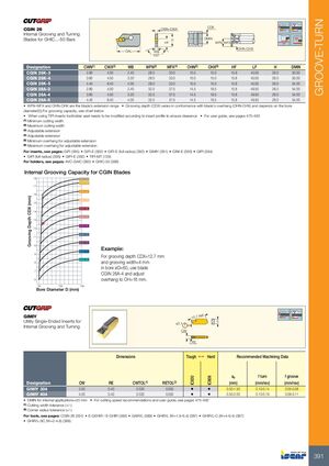
GROOVE-TURN
CGIN 26 — Державки для внутреннего нарезания канавок и обточки для пластин GHIC...-50
| Обозначение | CWN(1) | CWX(2) | WB | WFN(3) | WFX(4) | OHN(5) | OHX(6) | HF | LF | H | DMIN |
|---|---|---|---|---|---|---|---|---|---|---|---|
| CGIN 26K-3 | 2.80 | 4.00 | 2.40 | 28.0 | 33.0 | 10.0 | 15.0 | 15.8 | 45.00 | 26.0 | 50.00 |
| CGIN 26K-4 | 3.60 | 4.50 | 3.20 | 28.0 | 33.0 | 10.0 | 15.0 | 15.8 | 45.00 | 26.0 | 50.00 |
| CGIN 26K-5 | 4.40 | 6.40 | 4.00 | 28.0 | 33.0 | 10.0 | 15.0 | 15.8 | 45.00 | 26.0 | 54.00 |
| CGIN 26A-3 | 2.80 | 4.00 | 2.40 | 32.5 | 37.5 | 14.5 | 19.5 | 15.8 | 49.50 | 26.0 | 54.00 |
| CGIN 26A-4 | 3.60 | 4.50 | 3.20 | 32.5 | 37.5 | 14.5 | 19.5 | 15.8 | 49.50 | 26.0 | 54.00 |
| CGIN 26A-5 | 4.40 | 6.40 | 4.00 | 32.5 | 37.5 | 14.5 | 19.5 | 15.8 | 49.50 | 26.0 | 54.00 |
- WFN-WFX и OHN-OHX — диапазон удлинения пластины
- Глубина нарезания (CDX) варьируется в соответствии с выступом пластины (OHN-OHX) и зависит от диаметра отверстия (D). Для определения емкости нарезания см. график ниже
- При использовании пластин TIPI гнездо державки необходимо модифицировать в соответствии с профилем пластины для обеспечения зазора
- Руководство пользователя см. на стр. 475-492
(1) Минимальная ширина резания
(2) Максимальная ширина резания
(3) Регулируемое удлинение
(4) Регулируемое удлинение
(5) Минимальный выступ для регулируемого удлинения
(6) Максимальный выступ для регулируемого удлинения
Пластины см. на стр.: GIFI (395) • GIFI-E (392) • GIFI-E (полный радиус) (392) • GIMIY (391) • GINI-E (393) • GIPI (394) • GIPI (полный радиус) (395) • GIPI-E (392) • TIPI-MT (728)
Держатели см. на стр.: AVC-GAIC (390) • GHIC-50 (389)
Емкость нарезания канавок для пластин CGIN
Глубина нарезания CDX (мм) зависит от диаметра отверстия D (мм) и выступа (OH).
Пример: для глубины нарезания CDX = 12±7 мм и ширины нарезания = 4 мм в отверстии ø60 используйте пластину CGIN 26A-4 и отрегулируйте выступ на OH = 16 мм
GIMIY
Универсальные однорезные пластины для внутреннего нарезания канавок и обточки
| Обозначение | CW | RE | CWTOL(1) | RETOL(2) | IC830 | IC808 | ap (мм) | Подача поворот (мм/об) | Подача нарезание (мм/об) |
|---|---|---|---|---|---|---|---|---|---|
| GIMIY 304 | 3.00 | 0.40 | 0.020 | 0.050 | • | • | 0.50-1.50 | 0.10-0.14 | 0.05-0.08 |
| GIMIY 404 | 4.00 | 0.40 | 0.020 | 0.050 | • | • | 0.50-2.00 | 0.13-0.19 | 0.06-0.11 |
- DMIN для внутренних приложений = 20 мм
- Рекомендации по скорости резания и руководство пользователя см. на стр. 475-492
(1) Допуск ширины резания (+/-)
(2) Допуск радиуса угла (+/-)
Державки см. на стр.: CGIN 26 (391) • E-GEHIR / E-GHIR (383) • GAIR/L (389) • GHIR/L (W=1.9-6.4) (387) • GHIR/L-C (W=4-6.4) (387) • GHIR/L-SC (W=2-4.8) (388)