Инструмент для отрезки и обработки канавок Sandvik 2026 - страница 11
Навигация
 Новейший режущий инструмент и технологические решения Sandvik 2026
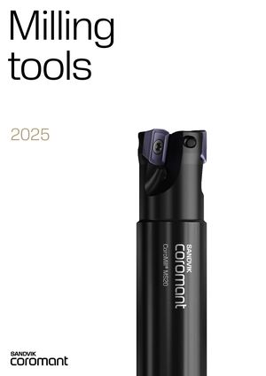 Фрезерный инструмент Sandvik 2026
 Дополнение к каталогам Sandvik 2021.1
 Каталог Sandvik дополнение 2018
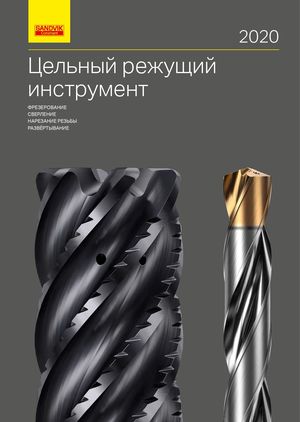 Каталог Sandvik цельный режущий инструмент 2020
 Дополнение к каталогам Sandvik 2022.1
- Selection guide
- CoroCut® 2
- Inserts
- CoroCut® 2, insert for parting
- CoroCut® 2, insert for grooving
- CoroCut® 1-2, insert for grooving
- CoroCut® 2, insert for turning
- CoroCut® 2, insert for profiling
- CoroCut® 1-2, insert for profiling
- Cutting units
- CoroCut® 2, cutting unit for parting and grooving
- CoroCut® 2, cutting unit for face grooving
- CoroCut® 2, cutting unit for profiling
- Shank tools
- CoroCut® 2, shank tool for parting and grooving
- CoroCut® 2, shank tool for shallow grooving
- CoroCut® 2, shank tool for face grooving
- CoroCut® 2, shank tool for profiling
- CoroCut® 2, QS™ shank tool for face grooving
- CoroCut® 2, QS™ shank tool for parting and grooving
- CoroCut® 2, QS™ shank tool for profiling
- Parting blades
- CoroCut® 2, blade for parting
- Cutting heads
- CoroCut® 2, cutting head for parting and grooving
- CoroCut® 2, cutting head for face grooving
- CoroCut® 2, QS™ Micro cutting head for parting and grooving
- Boring bars
- CoroCut® 2, boring bar for profiling
- CoroCut® 2, boring bar for internal grooving
- CoroCut® QD
- Inserts
- CoroCut® QD, insert for parting
- CoroCut® QD, insert for grooving
- CoroCut® QD, insert for turning
- CoroCut® QD, insert for profiling
- Cutting units
- CoroCut® QD, cutting unit for parting and grooving
- Shank tools
- CoroCut® QD, shank tool for Y-axis parting
- CoroCut® QD, QS™ shank tool for parting and grooving
- CoroCut® QD, shank tool for parting and grooving
- Parting blades
- CoroCut® QD, blade for Y-axis parting
- CoroCut® QD, blade for parting
- Cutting heads
- CoroCut® QD, cutting head for grooving
- CoroCut® QF
- Inserts
- CoroCut® QF, insert for face grooving
- Cutting units
- CoroCut® QF, cutting unit for face grooving
- Shank tools
- CoroCut® QF, shank tool for face grooving
- CoroCut® QF, QS™ shank tool for face grooving
- Cutting heads
- CoroCut® QF, cutting head for face grooving
- CoroCut® QI
- Inserts
- CoroCut® QI, inserts for grooving
- CoroCut® QI, insert for profiling
- Shank tools
- CoroCut® QI, shank tool for face grooving
- Cutting heads
- CoroCut® QI, cutting head for grooving
- CoroCut® QI, cutting head for face grooving
- Boring bars
- CoroCut® QI, boring bar for grooving
- CoroCut® QI, boring bar for face grooving
- CoroCut® 3
- Inserts
- CoroCut® 3, insert for parting
- CoroCut® 3, insert for grooving
- CoroCut® 3, insert for profiling
- Cutting units
- CoroCut® 3, cutting unit for parting and grooving
- Shank tools
- CoroCut® 3, shank tool for parting and grooving
- CoroCut® 3, QS™ shank tool for parting and grooving
- Cutting heads
- CoroCut® 3, cutting head for grooving
- CoroCut® MB
- Inserts
- CoroCut® MB, solid carbide head for pre-parting
- CoroCut® MB, solid carbide head for grooving
- CoroCut® MB, solid carbide head for profiling
- CoroCut® MB, solid carbide head for face grooving
- Adaptors
- Adaptor with cylindrical shank coupling to CoroCut® MB
- Adaptor with cylindrical shank with flat coupling to CoroCut® MB
- Adaptor with rectangular shank to CoroCut® MB
- CoroCut® XS
- Inserts
- CoroCut® XS, insert for parting
- CoroCut® XS, insert for grooving
- CoroCut® XS, insert for profiling
- Cutting heads
- CoroCut® XS, QS™ Micro cutting head for parting and grooving
- CoroCut® XS, QS™ Micro cutting head for Y-axis parting and grooving
- CoroCut® XS, cutting head for grooving
- Shank tools
- CoroCut® XS, QS™ shank tool for parting and grooving
- CoroCut® XS, shank tool for parting and grooving
- CoroTurn® XS
- Inserts
- CoroTurn® XS, solid carbide tool for pre-parting
- CoroTurn® XS, solid carbide tool for grooving
- CoroTurn® XS, solid carbide tool for profiling
- CoroTurn® XS, solid carbide tool for face grooving
- Adaptors
- Adaptor with rectangular shank coupling to CoroTurn® XS
- Cylindrical shank with flat to CoroTurn® XS adaptor
- Cylindrical shank with flat to CoroTurn® XS double-ended adaptor
- Cylindrical shank with flat to CoroTurn® XS adaptor
- Cylindrical shank with flat to CoroTurn® XS double-ended adaptor
- Coromant Capto® to CoroTurn® XS adaptor
- General information
- Coolant supply information
- Cutting tool parameters according to ISO 13399
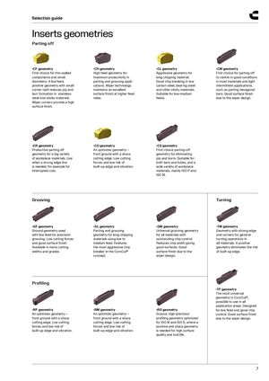
Inserts geometries
Parting off
| -CF geometry | -CH geometry | -CL geometry | -CM geometry |
| First choice for thin-walled | High feed geometry for | Aggressive geometry for | First choice for parting off |
| components and small | maximum productivity in | long chipping material. | to centre in good conditions |
| diameters. A low feed, | parting and grooving appli- | Good chip breaking in low | in most materials and light |
| positive geometry with small | cations. Wiper technology | carbon steel, bearing steel | intermittent applications, |
| corner radii reduces pip and | maintains an excellent | and other sticky materials. | such as parting hexagonal |
| burr formation in stainless | surface finish at higher feed | Suitable for low-medium | bars. Good surface finish |
| steel and sticky materials. | rates. | feeds. | due to the wiper design. |
Wiper corners provide a high surface finish.
| -CR geometry | -CO geometry | -CS geometry |
| Productive parting off | An optimizer geometry – | First choice parting-off |
| geometry for a big variety | front ground with a sharp | geometry for eliminating |
| of workpiece materials. Use | cutting edge. Low cutting | pip and burrs. Suitable for |
| when a strong edge line | forces and low risk of | both bars and tubes, and a |
| is needed, for example for | built-up edge and vibration. | wide variety of workpiece |
interrupted cuts. materials, mainly ISO P and ISO M.
Grooving Turning
| -GF geometry | -GL geometry | -GM geometry | -TM geometry |
| Ground geometry used | Parting and grooving | Universal grooving geometry | Geometry with strong edge |
| with low feed for precision | geometry for long chipping | for all materials with | and corners for general |
| grooving. Low cutting forces | materials using low to | outstanding chip control. | turning operations in |
| and good surface finish. | medium feed. Features | Reduces chip width giving | all materials. A positive |
| Available in many cutting | the most aggressive chip | good surfaces. Good | geometry eliminates the risk |
| widths and grades. | breaker in the CoroCut® | surface finish due to the | of built-up edge. |
concept. wiper design.
Profiling
| -RF geometry | -RM geometry | -RO geometry |
| An optimizer geometry – | An optimizer geometry – | Ground, high-precision |
| front ground with a sharp | front ground with a sharp | profiling geometry optimized |
| cutting edge. Low cutting | cutting edge. Low cutting | for ISO M and ISO S, where a |
| forces and low risk of | forces and low risk of | positive and sharp geometry |
| built-up edge and vibration. | built-up edge and vibration. | is needed for high surface |
quality and tool life.
-TF geometry The most universal geometry in CoroCut®, possible to use in all application areas. Designed for low feed and good chip control. Good surface finish due to the wiper design.