Каталог Sumitomo фрезы со сменными пластинами - страница 97
Навигация
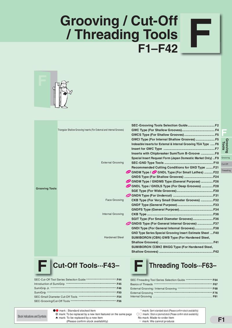 Каталог Sumitomo инструмент для обработки канавок
 Общий каталог Sumitomo 2019 - 2020
 Каталог Sumitomo модульные системы для револьверных головок токарных станков
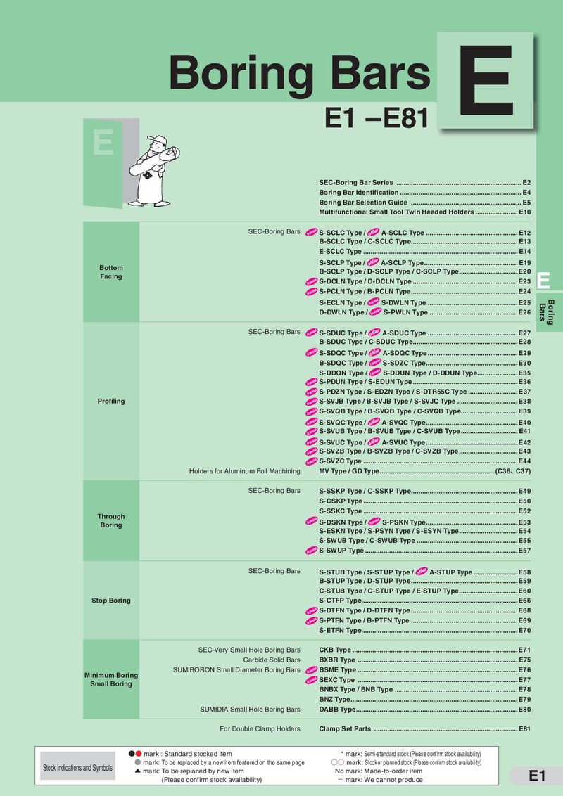 Каталог Sumitomo токарные резцы (державки) для внутреннего точения
 Общий каталог Sumitomo 2018 - 2019
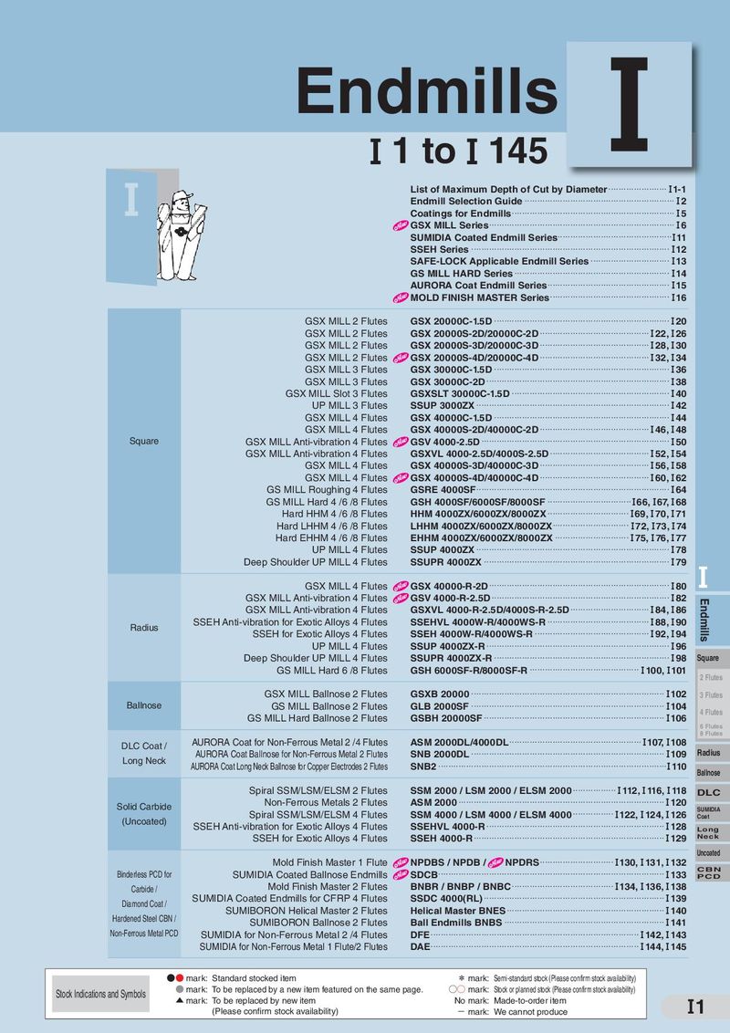 Каталог Sumitomo монолитные фрезы
- H001
- H002
- H003
- H004
- H005
- H006
- H007
- H008
- H009
- H010
- H011
- H012
- H013
- H014
- H015
- H016
- H017
- H018
- H019
- H020
- H021
- H022
- H023
- H024
- H025
- H026
- H027
- H028
- H029
- H030
- H031
- H032
- H033
- H034
- H035
- H036
- H037
- H038
- H039
- H040
- H041
- H042
- H043
- H044
- H045
- H046
- H047
- H048
- H049
- H050
- H051
- H052
- H053
- H054
- H055
- H056
- H057
- H058
- H059
- H060
- H061
- H062
- H063
- H064
- H065
- H066
- H067
- H068
- H069
- H070
- H071
- H072
- H073
- H074
- H075
- H076
- H077
- H078
- H079
- H080
- H081
- H082
- H083
- H084
- H085
- H086
- H087
- H088
- H089
- H090
- H091
- H092
- H093
- H094
- H095
- H096
- H097
- H098
- H099
- H100
- H101
- H102
- H103
- H104
- H105
- H106
- H107
- H108
- H109
- H110
- H111
- H112
- H113
- H114
- H115
- H116
- H117
- H118
- H119
- H120
- H121
- H122
- H123
- H124
- H125
- H126
- H127
- H128
- H129
- H130
- H131
- H132
- H133
- H134
- H135
- H136
- H137
- H138
- H139
- H140
- H141
- H142
- H143
- H144
- H145
- H146
- H147
- H148
- H149
- H150
- H151
- H152
- H153
- H154
- H155
- H156
- H157
- H158
- H159
- H160
- H161
- H162
- H163
- H164
- H165
- H166
- H167
- H168
- H169
- H170
- H171
- H172
- H173
- H174
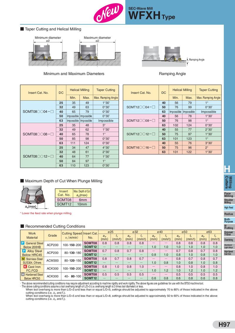
SEC-Wave Mill WFXH Type ■ Taper Cutting and Helical Milling Minimum diameter Maximum diameter øD øD Ramping Angle Minimum and Maximum Diameters Ramping Angle Insert Cat. No. DC Helical Milling Taper Cutting Insert Cat. No. DC Helical Milling Taper Cutting Min. Max. Max. Ramping Angle Min. Max. Max. Ramping Angle 25 35 49 1°30’ 40 56 79 1° 32 49 63 0°30’ SOMT12○○04−□ 50 76 99 0°30’ SOMT08○○04−□ 40 65 79 0°30’ 63 Impossible Impossible Impossible 50 Impossible Impossible 0°30’ 40 56 78 1°30’ 63 Impossible Impossible Impossible SOMT12○○08−□ 50 76 98 1° 25 35 48 3° 63 102 124 0°30’ 32 49 62 1°30’ 40 55 77 2°30’ SOMT08○○08−□ 40 65 78 1° SOMT12○○12−□ 50 75 97 1°30’ 50 85 98 0°30’ 63 101 123 1° 63 111 124 0°30’ 40 55 76 3°30’ 25 34 47 4°30’ SOMT16○○16−□ 50 75 96 2° 32 48 61 2°30’ 63 101 122 1°30’ SOMT08○○12−□ 40 64 77 1°30’ 50 84 97 1° 63 110 123 0°30’ H ■ Maximum Depth of Cut When Plunge Milling Cutters Milling Insert Max. Depth of Cut Face Cat. No. ae(max) Milling SOMT08 6mm Shoulder Milling SOMT12 10mm ae(max) High Feed * Lower the feed rate when plunge milling. Radius Multi- Purpose ■ Recommended Cutting Conditions R/ Profiling Work Cutting Speed Insert Cat. ø25 ø32 ø40 ø50 ø63 Groove/ Grade ap fz ap fz ap fz ap fz ap fz T-Slot Material v(c m/min) No. (mm) (mm/t) (mm) (mm/t) (mm) (mm/t) (mm) (mm/t) (mm) (mm/t) Chamfering P General Steel ACP200 100-150-200 SOMT08 0.8 0.8 0.8 0.8 Q Q 0.8 0.8 0.8 0.8 Aluminum/ Below 200HB SOMT12 Q Q Q Q 1.0 1.0 1.0 1.0 1.0 1.0 Light Alloys P Alloy Steel ACP200 80-130-180 SOMT08 0.7 0.8 0.7 0.8 Q Q 0.7 0.8 0.7 0.8 High-Speed Below HRC45 SOMT12 Q Q Q Q 0.8 1.0 0.8 1.0 0.8 1.0 Cast Iron M Stainless Steel ACM300 80-120-150 SOMT08 0.8 0.7 0.8 0.7 Q Q 0.8 0.7 0.8 0.7 SUS304, Others SOMT12 Q Q Q Q 1.0 0.8 1.0 0.8 1.0 0.8 K Cast Iron ACK300 100-150-200 SOMT08 0.8 1.0 0.8 1.0 Q Q 0.8 1.0 0.8 1.0 FC,FCD SOMT12 Q Q Q Q 1.0 1.2 1.0 1.2 1.0 1.2 H Hardened Steel ACK300 40- 80-100 SOMT08 0.5 0.5 0.5 0.5 Q Q 0.5 0.5 0.5 0.5 Below HRC50 SOMT12 Q Q Q Q 0.6 0.8 0.6 0.8 0.6 0.8 ・The above recommended cutting conditions may require adjustment according to machine rigidity and work rigidity. The above figures are guidelines for use with the BT50 machine tool. ・The above cutting conditions assume a tool overhang length of L/D=3 (i.e. overhang length is 3 times tool diameter) or less. When tool overhang is more than L/D=3 and less than or equal L/D=5, settings should be adjusted to approximately 70 to 80% of those indicated in the above cutting conditions (i.e. ap and fz). When tool overhang is more than L/D=5 and less than or equal L/D=8, settings should be adjusted to approximately 50 to 60% of those indicated in the above cutting conditions (i.e. ap and fz). H97