Каталог Sumitomo фрезы со сменными пластинами - страница 119
Навигация
 Каталог Sumitomo инструмент для обработки канавок
 Общий каталог Sumitomo 2019 - 2020
 Каталог Sumitomo модульные системы для револьверных головок токарных станков
 Каталог Sumitomo токарные резцы (державки) для внутреннего точения
 Общий каталог Sumitomo 2018 - 2019
 Каталог Sumitomo монолитные фрезы
- H001
- H002
- H003
- H004
- H005
- H006
- H007
- H008
- H009
- H010
- H011
- H012
- H013
- H014
- H015
- H016
- H017
- H018
- H019
- H020
- H021
- H022
- H023
- H024
- H025
- H026
- H027
- H028
- H029
- H030
- H031
- H032
- H033
- H034
- H035
- H036
- H037
- H038
- H039
- H040
- H041
- H042
- H043
- H044
- H045
- H046
- H047
- H048
- H049
- H050
- H051
- H052
- H053
- H054
- H055
- H056
- H057
- H058
- H059
- H060
- H061
- H062
- H063
- H064
- H065
- H066
- H067
- H068
- H069
- H070
- H071
- H072
- H073
- H074
- H075
- H076
- H077
- H078
- H079
- H080
- H081
- H082
- H083
- H084
- H085
- H086
- H087
- H088
- H089
- H090
- H091
- H092
- H093
- H094
- H095
- H096
- H097
- H098
- H099
- H100
- H101
- H102
- H103
- H104
- H105
- H106
- H107
- H108
- H109
- H110
- H111
- H112
- H113
- H114
- H115
- H116
- H117
- H118
- H119
- H120
- H121
- H122
- H123
- H124
- H125
- H126
- H127
- H128
- H129
- H130
- H131
- H132
- H133
- H134
- H135
- H136
- H137
- H138
- H139
- H140
- H141
- H142
- H143
- H144
- H145
- H146
- H147
- H148
- H149
- H150
- H151
- H152
- H153
- H154
- H155
- H156
- H157
- H158
- H159
- H160
- H161
- H162
- H163
- H164
- H165
- H166
- H167
- H168
- H169
- H170
- H171
- H172
- H173
- H174
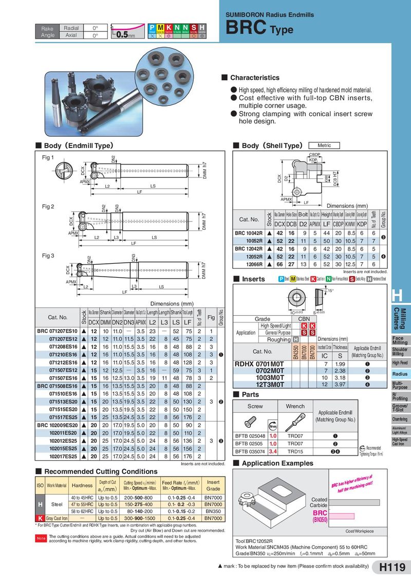
SUMIBORON Radius Endmills Rake Radial 0° P MKNN SH BRC Type Angle Axial 0.5mm Steel Stainless Steel Cast Iron Non-Ferrous Metal Aluminum Exotic Alloy Hardened Steel 0° H H G S G ■ Characteristics ● High speed, high efficiency milling of hardened mold material. ● Cost effective with full-top CBN inserts, multiple corner usage. ● Strong clamping with conical insert screw hole design. ■ Body(Endmill Type) ■ Body(Shell Type) Metric Fig 1 DN2 CBDP KDP DCX h7 DMM DCX D2 KWW DCB H7 APMX l LS L2 LF APMX LF Fig 2 DN2 DN3 Dimensions (mm) DCX DMM h7 Cat. No. Stock Max.Diameter Hole Size Bolt Max.DepthofCut Height MountingDepth GroovingWidth GroovingDepth No. of Teeth Group No. DCX DCB D2 APMX LF CBDP KWW KDP APMX l L2 L3 LS BRC 10042R F 42 16 9 5 44 20 8.5 6 6 ❸ LF 10052R F 52 22 11 5 50 30 10.5 7 7 BRC 12042R F 42 16 9 6 42 20 8.5 6 5 Fig 3 DN2 DN3 12052R F 52 22 11 6 52 30 10.5 7 5 ❹ DCX DMM h7 12066R F 66 27 13 6 52 30 12.5 7 6 Inserts are not included. APMlX ■ Inserts P Steel M Stainless Steel K Cast Iron N Non-Ferrous Metal S Exotic Al oy H Hardened Steel L2 L3 LS LF 15° H Dimensions (mm) Stock Max.Diameter Shank Diameter Diameter Max.DepthofCut Length Length Shank TotalLength No. of Teeth Group No. IC±0.013 S±0.025 Cutters Milling Cat. No. DCX DMM DN2 DN3 APMX L2 L3 LS LF Fig Grade CBN High Speed/Light K K BRC 071207ES10 F 12 10 11.0 Q 3.5 23 Q 52 75 2 1 Application General Purpose S S 071207ES12 F 12 12 11.0 11.5 3.5 22 8 45 75 2 2 Roughing H Dimensions (mm) Face Milling 071208ES16 F 12 16 11.0 15.5 3.5 16 8 48 88 2 3 Cat. No. BN350 BN7000 BN700 InscribedCircle Thickness Applicable Endmill Shoulder 071210ES16 F 12 16 11.0 15.5 3.5 16 8 48 108 2 3 ❶ IC S (Matching Group No.) Milling 071212ES16 F 12 16 11.0 15.5 3.5 16 8 48 128 2 3 RDHX 0701M0T 7 1.99 ❶ High Feed 071507ES12 F 15 12 12.5 Q 3.5 16 Q 59 75 3 1 0702M0T 7 2.38 ❷ Radius 071507ES16 F 15 16 12.5 13.0 3.5 19 11 48 78 3 2 1003M0T 10 3.18 ❸ BRC 071508ES16 F 15 16 13.5 15.5 3.5 20 8 48 88 2 12T3M0T 12 3.97 ❹ Multi- Purpose 071510ES16 F 15 16 13.5 15.5 3.5 20 8 48 108 2 ■ Parts R/ 071513ES20 F 15 20 13.5 19.5 3.5 22 8 50 130 2 3 ❷ Profiling 071515ES20 F 15 20 13.5 19.5 3.5 22 8 50 150 2 Screw Wrench Groove/ T-Slot Applicable Endmill 071517ES25 F 15 25 13.5 24.5 3.5 22 8 56 176 2 (Matching Group No.) Chamfering BRC 102009ES20 F 20 20 17.0 19.5 5.0 20 8 50 90 2 Nm Aluminum/ 102011ES20 F 20 20 17.0 19.5 5.0 22 8 50 110 2 BFTB 025048 1.0 TRD07 Light Alloys ❶ High-Speed 102012ES25 F 20 25 17.0 24.5 5.0 24 8 56 136 2 3 ❸ BFTB 02505 1.0 TRD07 ❷ Cast Iron 102015ES25 F 20 25 17.0 24.5 5.0 24 8 56 156 2 BFTB 035074 3.4 TRD15 ❸❹ N m Recommended 102017ES25 F 20 25 17.0 24.5 5.0 24 8 56 176 2 Tightening Torque(N・m) Inserts are not included. ■ Application Examples ■ Recommended Cutting Conditions BRChhaalsf thhieghmearcehffiinciinegnccyosatt! ISO Work Material Hardness Depth of Cut Cutting Speed v(c m/min) Feed Rate f(z mm/t) Insert a(p mm) Min.- Optimum -Max. Min.- Optimum -Max. Grade 40 to 45HRC Up to 0.5 200-500-800 0.1- 0.25 -0.4 BN7000 Coated H Steel 47 to 55HRC Up to 0.5 150- 275 -400 0.1- 0.2 -0.3 BN7000 Carbide 58 to 62HRC Up to 0.5 80- 140 -200 0.1- 0.15 -0.2 BN350 BRC K Gray Cast Iron Q Up to 0.5 300-900-1500 0.1- 0.25 -0.4 BN7000 (BN350) * For BRC Type Cutter/Endmill and RDHX Type Inserts, use in combination with applicable group numbers. Dry cut (Air Blow) and Down cut are recommended. Cost/Workpiece Note The cutting conditions above are a guide. Actual conditions will need to be adjusted according to machine rigidity, work clamp rigidity, cutting depth, and other factors. Too:l BRC12052R Work Materia:l SNCM435 (Machine Component) 55 to 60HRC Grade:BN350 vC=250m/min fz=0.1mm/t ap=0.5mm ae=50mm F mark : To be replaced by new item (Please confirm stock availability) H119