Каталог Sumitomo фрезы со сменными пластинами - страница 60
Навигация
 Каталог Sumitomo инструмент для обработки канавок
 Общий каталог Sumitomo 2019 - 2020
 Каталог Sumitomo модульные системы для револьверных головок токарных станков
 Каталог Sumitomo токарные резцы (державки) для внутреннего точения
 Общий каталог Sumitomo 2018 - 2019
 Каталог Sumitomo монолитные фрезы
- H001
- H002
- H003
- H004
- H005
- H006
- H007
- H008
- H009
- H010
- H011
- H012
- H013
- H014
- H015
- H016
- H017
- H018
- H019
- H020
- H021
- H022
- H023
- H024
- H025
- H026
- H027
- H028
- H029
- H030
- H031
- H032
- H033
- H034
- H035
- H036
- H037
- H038
- H039
- H040
- H041
- H042
- H043
- H044
- H045
- H046
- H047
- H048
- H049
- H050
- H051
- H052
- H053
- H054
- H055
- H056
- H057
- H058
- H059
- H060
- H061
- H062
- H063
- H064
- H065
- H066
- H067
- H068
- H069
- H070
- H071
- H072
- H073
- H074
- H075
- H076
- H077
- H078
- H079
- H080
- H081
- H082
- H083
- H084
- H085
- H086
- H087
- H088
- H089
- H090
- H091
- H092
- H093
- H094
- H095
- H096
- H097
- H098
- H099
- H100
- H101
- H102
- H103
- H104
- H105
- H106
- H107
- H108
- H109
- H110
- H111
- H112
- H113
- H114
- H115
- H116
- H117
- H118
- H119
- H120
- H121
- H122
- H123
- H124
- H125
- H126
- H127
- H128
- H129
- H130
- H131
- H132
- H133
- H134
- H135
- H136
- H137
- H138
- H139
- H140
- H141
- H142
- H143
- H144
- H145
- H146
- H147
- H148
- H149
- H150
- H151
- H152
- H153
- H154
- H155
- H156
- H157
- H158
- H159
- H160
- H161
- H162
- H163
- H164
- H165
- H166
- H167
- H168
- H169
- H170
- H171
- H172
- H173
- H174
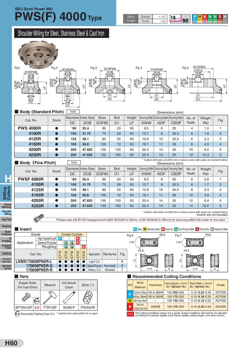
SEC-Sumi Power Mill PWS(F) 4000 Type Rake Radial 㸫15° 16mm P MKN NSH Angle Axial 㸫6° 90°Steel Stainless Steel Cast Iron Non-FerrousMetal Aluminum Exotic Alloy Hardened Steel G S G Shoulder Milling for Steel, Stainless Steel & Cast Iron Fig1 Fig 2 DCSFMS Fig 3 DCSFMS Fig 4 DCSFMS Fig 5 DCSFMS DCSFMS DCB DCB DCB ø101.6 DCB KWW KWW KWW DCB KWW KWW CBDP KDP CBDP KDP CBDP KDP CBDP KDP CBDP KDP LF LF LF LF LF ø30 ø13 ø17 D1 D1 D1 D1 D1 DC DC DC DC ø46 DC ■ Body (Standard Pitch) Inch Dimensions (mm) Cat. No. Stock Diameter Hole Size Boss Bolt Height Grooving Width Grooving Depth Mounting Depth No. of Weight Fig DC DCB DCSFMS D1 LF KWW KDP CBDP Teeth (kg) PWS 4080R D *80 25.4 60 20 50 9.5 6 25 4 1.0 1 4100R D *100 31.75 70 28 63 12.7 8 32.5 6 1.8 2 4125R D 125 38.1 80 55 63 15.9 10 35.5 6 2.4 3 4160R D 160 50.8 100 72 63 19.1 11 38 8 4.0 4 4200R D 200 47.625 130 130 63 25.4 14 35 10 6.5 5 4250R D 250 47.625 130 160 63 25.4 14 35 12 12.3 5 ■ Body(Fine Pitch) * Cutters with sizes of ø200 mm or above come with seats (no coolant holes). Inch Dimensions (mm) Cat. No. Stock Diameter Hole Size Boss Bolt Height Grooving Width Grooving Depth Mounting Depth No. of Weight Fig H DC DCB DCSFMS D1 LF KWW KDP CBDP Teeth (kg) PWSF 4080R D *80 25.4 60 20 50 9.5 6 25 6 0.9 1 4100R D *100 31.75 70 28 63 12.7 8 32.5 8 1.7 2 Milling Cutters 4125R D 125 38.1 80 55 63 15.9 10 35.5 8 2.3 3 4160R D 160 50.8 100 72 63 19.1 11 38 10 3.9 4 4200R D 200 47.625 130 130 63 25.4 14 35 12 6.4 5 Face 4250R D 250 47.625 130 160 63 25.4 14 35 14 12.2 5 Milling Shoulder * Cutters with sizes of ø200 mm or above come with seats (no coolant holes). Milling Inserts are not included. High Feed *Please use JIS B1176 hexagonal bolt (ø80: M12x30 to 35mm, ø100: M16x40 to 45mm) for securing ø80/ø100 cutter to the arbor. Radius ■ Insert P Steel M Stainless Steel K Cast Iron N Non-Ferrous Metal S Exotic Alloy H Hardened Steel Multi- Grade Coated Carbide Purpose Fig 6 R0.8 Fig 7 R0.8 R/ High Speed/Light P K Profiling Application General Purpose K 176 176 Groove/ Roughing K T-Slot ø4.6 ø4.6 ACP100 ACP200 ACP300 ACK200 ACK300 Chamfering Cat. No. Application Remarks Fig Aluminum/ LNMX170808PNSR-L 13 13 Light Alloys D D D D D Light Cut 6 High-Speed 170808PNSR-G D D D D D General Purpose Recommended 6 Cast Iron 170808PNSR-R D D D D D Heavy Cut Nicked 7 17.2 8 17.2 8 ■ Parts ■ Recommended Cutting Conditions Stopper Screw Wrench Anti-seizure Shim (*) ISO Work Hardness Cutting Speed v(c m/min) Feed Rate f(z mm/t) Grade (For Insert/Shim) Cream Material Min.- Optimum -Max. Min.- Optimum -Max. P Carbon Stee 180 to 280HB 150- 250 -350 0.10- 0.23 -0.35 ACP200 Alloy Steel 180 to 280HB 100- 175 -250 0.10- 0.18 -0.25 ACP200 Nm M Stainless Steel Q 100- 150 -200 0.10- 0.18 -0.25 ACP300 BFTX0412IP 3.0 TTR15IP SUMI-P PWSS4R K Cast Iron 250HB 100- 175 -250 0.10- 0.23 -0.35 ACK200 Ductile Cast Iron N m Recommended Tightening Torque(N・m) * Included with cutters ø200 mm or larger Note The cutting conditions above are a guide. Actual conditions will need to be adjusted according to machine rigidity, work clamp rigidity, cutting depth, and other factors. H60