Каталог Sumitomo фрезы со сменными пластинами - страница 112
Навигация
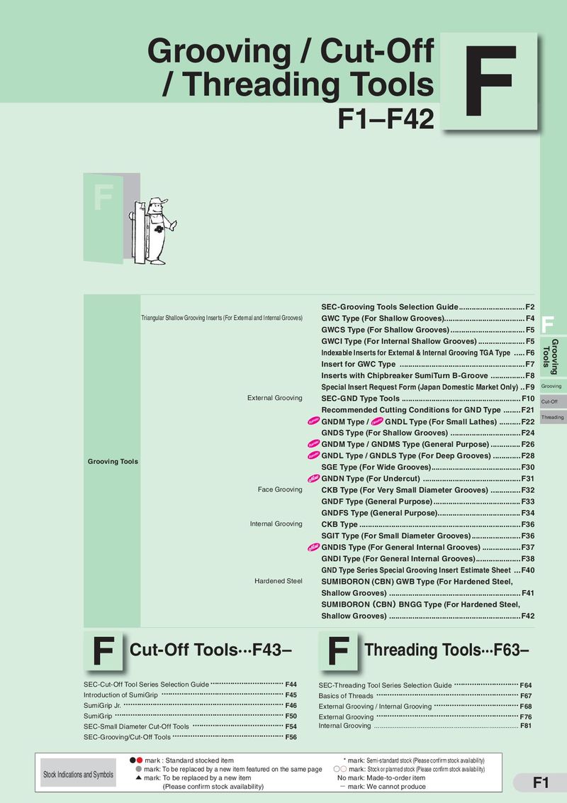 Каталог Sumitomo инструмент для обработки канавок
 Общий каталог Sumitomo 2019 - 2020
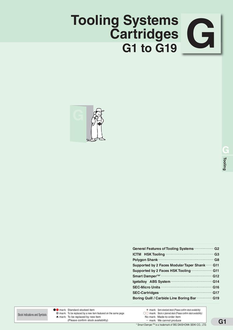 Каталог Sumitomo модульные системы для револьверных головок токарных станков
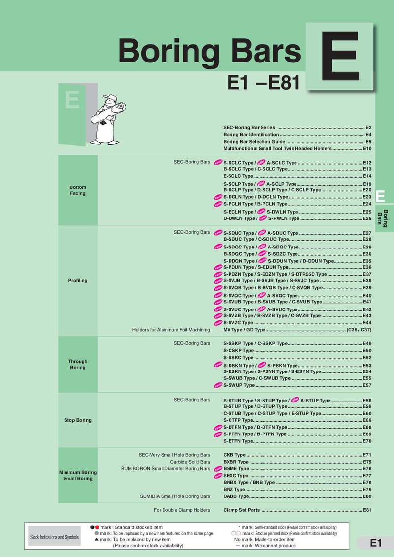 Каталог Sumitomo токарные резцы (державки) для внутреннего точения
 Общий каталог Sumitomo 2018 - 2019
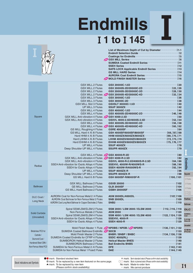 Каталог Sumitomo монолитные фрезы
- H001
- H002
- H003
- H004
- H005
- H006
- H007
- H008
- H009
- H010
- H011
- H012
- H013
- H014
- H015
- H016
- H017
- H018
- H019
- H020
- H021
- H022
- H023
- H024
- H025
- H026
- H027
- H028
- H029
- H030
- H031
- H032
- H033
- H034
- H035
- H036
- H037
- H038
- H039
- H040
- H041
- H042
- H043
- H044
- H045
- H046
- H047
- H048
- H049
- H050
- H051
- H052
- H053
- H054
- H055
- H056
- H057
- H058
- H059
- H060
- H061
- H062
- H063
- H064
- H065
- H066
- H067
- H068
- H069
- H070
- H071
- H072
- H073
- H074
- H075
- H076
- H077
- H078
- H079
- H080
- H081
- H082
- H083
- H084
- H085
- H086
- H087
- H088
- H089
- H090
- H091
- H092
- H093
- H094
- H095
- H096
- H097
- H098
- H099
- H100
- H101
- H102
- H103
- H104
- H105
- H106
- H107
- H108
- H109
- H110
- H111
- H112
- H113
- H114
- H115
- H116
- H117
- H118
- H119
- H120
- H121
- H122
- H123
- H124
- H125
- H126
- H127
- H128
- H129
- H130
- H131
- H132
- H133
- H134
- H135
- H136
- H137
- H138
- H139
- H140
- H141
- H142
- H143
- H144
- H145
- H146
- H147
- H148
- H149
- H150
- H151
- H152
- H153
- H154
- H155
- H156
- H157
- H158
- H159
- H160
- H161
- H162
- H163
- H164
- H165
- H166
- H167
- H168
- H169
- H170
- H171
- H172
- H173
- H174
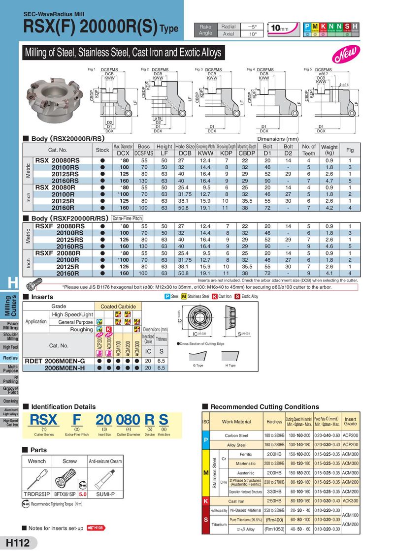
SEC-WaveRadius Mill RSX(F) 20000R(S)Type Rake Radial −5° 10mm P MKN N S H Angle Steel Stainless Steel Cast Iron Non-Ferrous Metal Aluminum Exotic Alloy Hardened Steel Axial 10° G G G G Milling of Steel, Stainless Steel, Cast Iron and Exotic Alloys Fig 1 DCSFMS Fig 2 DCSFMS Fig 3 DCSFMS Fig 4 DCSFMS Fig 5 DCSFMS DCB DCB DCB DCB ø66.7 KWW KWW KWW KWW DCB KDP KWW 4-ø14 CBDP KDP CBDP LF CBDP KDP CBDP KDP CBDP KDP LF LF LF LF ø18 D2 D2 D1 D1 D1 D1 D1 DCX DCX DCX DCX DCX ■ Body(RSX20000R/RS) Dimensions (mm) Cat. No. Stock Max. Diameter Boss Height Hole Size Grooving Width Grooving Depth Mounting Depth Bolt Bolt No. of Weight Fig DCX DCSFMS LF DCB KWW KDP CBDP D1 D2 Teeth (kg) RSX 20080RS D *80 55 50 27 12.4 7 22 20 14 4 0.9 1 Metric 20100RS D 100 70 50 32 14.4 8 32 46 - 5 1.8 3 20125RS D 125 80 63 40 16.4 9 29 52 29 6 2.6 1 20160RS D 160 130 63 40 16.4 9 29 90 - 7 4.7 5 RSX 20080R D *80 55 50 25.4 9.5 6 25 20 14 4 0.9 1 Inch 20100R D *100 70 63 31.75 12.7 8 32 46 27 5 1.8 2 20125R D 125 80 63 38.1 15.9 10 35.5 55 30 6 2.6 1 20160R D 160 100 63 50.8 19.1 11 38 72 - 7 4.2 4 ■ Body(RSXF20000R/RS)Extra-Fine Pitch RSXF 20080RS D *80 55 50 27 12.4 7 22 20 14 5 0.9 1 Metric 20100RS D 100 70 50 32 14.4 8 32 46 - 6 1.8 3 20125RS D 125 80 63 40 16.4 9 29 52 29 7 2.6 1 20160RS D 160 130 63 40 16.4 9 29 90 - 9 4.6 5 RSXF 20080R D *80 55 50 25.4 9.5 6 25 20 14 5 0.9 1 Inch 20100R D *100 70 63 31.75 12.7 8 32 46 27 6 1.8 2 20125R D 125 80 63 38.1 15.9 10 35.5 55 30 7 2.6 1 20160R D 160 100 63 50.8 19.1 11 38 72 - 9 4.1 4 H Inserts are not included. Check the arbor attachment size (DCB) when selecting the cutter. *Please use JIS B1176 hexagonal bolt (ø80: M12x30 to 35mm, ø100: M16x40 to 45mm) for securing ø80/ø100 cutter to the arbor. Milling Cutters ■ Inserts P Steel M Stainless Steel K Cast Iron S Exotic Alloy Grade Coated Carbide High Speed/Light IC±0.025 Face Application General Purpose Milling Roughing K Dimensions (mm) Shoulder Inscribed IC±0.025 S±0.025 Milling ACP200 ACK300 Circle Thickness High Feed Cat. No. ACM100 ACM200 ACM300 ●Cross Section of Cutting Edge IC S Radius RDET 2006M0EN-G D D D D D 20 6.5 Multi- 2006M0EN-H D D D D D 20 6.5 G Type H Type Purpose R/ Profiling Groove/ T-Slot Chamfering Aluminum/ ■ Identification Details ■ Recommended Cutting Conditions Light Alloys RSX F 20 080 R S High-Speed ISO Work Material Hardness Cutting Speed (c m/min) Feed Rate (z mm/t) Insert Cast Iron Min.- Optimum- Max. Min.- Optimum- Max. Grade (1) (2) (3) (4) (5) (6) Cutter Series Extra-Fine Pitch Insert Size Cutter Diameter Direction Metric Bore Carbon Steel 180 to 280HB 100-160-200 0.20-0.40- 0.60 ACP200 P 180 to 280HB 100-140-180 0.20-0.30- 0.40 ACP200 Alloy Steel ■ Parts Ferritic 200HB 150-180-200 0.15-0.25- 0.35 ACM300 Wrench Screw Anti-seizure Cream Stainless Steel Cr Martensitic 200 to 330HB 80-120-180 0.15-0.25- 0.35 ACM300 M Austenitic 200HB 150-180-200 0.15-0.25- 0.35 ACM300 Cr-Ni 2 Phase Structures 230 to 270HB 80-120-180 0.15-0.25- 0.35 ACM200 Nm (Austenitic・Ferritic) TRDR25IP BFTX0615IP 5.0 SUMI-P Deposition Hardened Structures 330HB 60-100-160 0.15-0.25- 0.35 ACM200 N m Recommended Tightening Torque(N・m) K Cast Iron 250HB 80-120-160 0.10-0.30- 0.40 ACK300 Heat-Resistant Aloy Ni-Based Material 250 to 350HB 20- 30 - 40 0.10-0.20- 0.30 ACM100 S Pure Titanium (99.5%) (Rm400) 60- 80 -100 0.10-0.20- 0.30 ■ Notes for inserts set-up H108 Titanium ACM200 α+β Alloy (Rm1050) 40- 50 - 60 0.10-0.20- 0.30 H112