Каталог Sumitomo фрезы со сменными пластинами - страница 50
Навигация
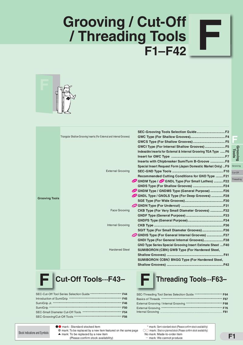 Каталог Sumitomo инструмент для обработки канавок
 Общий каталог Sumitomo 2019 - 2020
 Каталог Sumitomo модульные системы для револьверных головок токарных станков
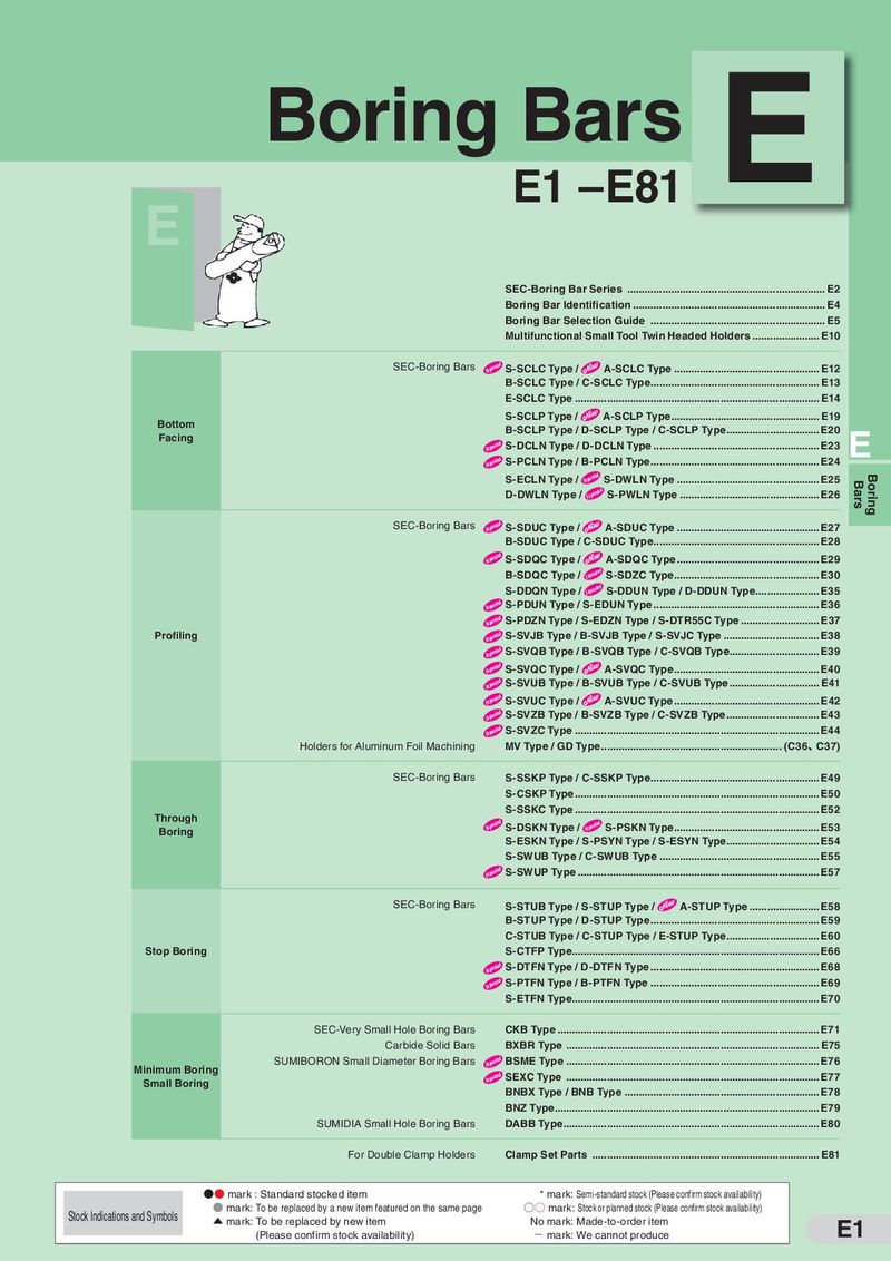 Каталог Sumitomo токарные резцы (державки) для внутреннего точения
 Общий каталог Sumitomo 2018 - 2019
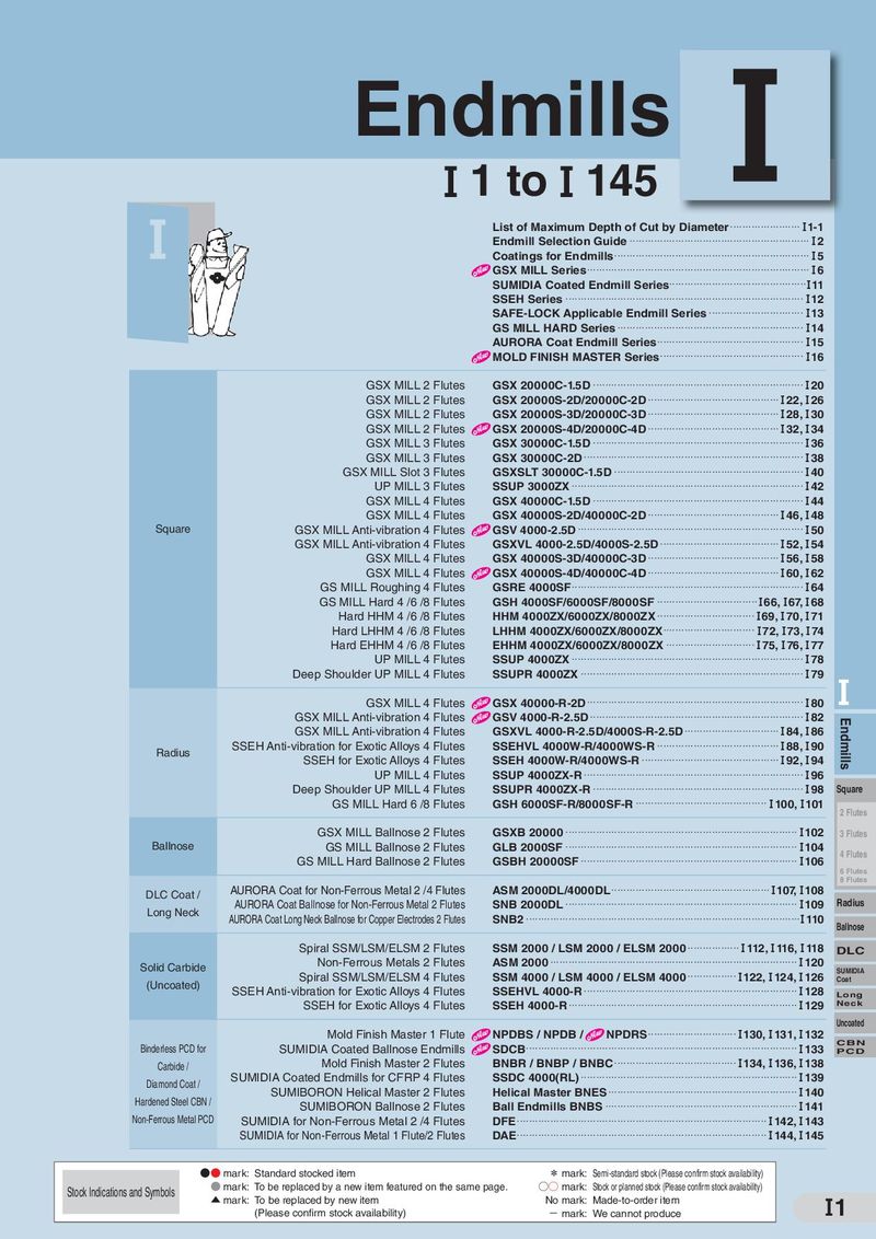 Каталог Sumitomo монолитные фрезы
- H001
- H002
- H003
- H004
- H005
- H006
- H007
- H008
- H009
- H010
- H011
- H012
- H013
- H014
- H015
- H016
- H017
- H018
- H019
- H020
- H021
- H022
- H023
- H024
- H025
- H026
- H027
- H028
- H029
- H030
- H031
- H032
- H033
- H034
- H035
- H036
- H037
- H038
- H039
- H040
- H041
- H042
- H043
- H044
- H045
- H046
- H047
- H048
- H049
- H050
- H051
- H052
- H053
- H054
- H055
- H056
- H057
- H058
- H059
- H060
- H061
- H062
- H063
- H064
- H065
- H066
- H067
- H068
- H069
- H070
- H071
- H072
- H073
- H074
- H075
- H076
- H077
- H078
- H079
- H080
- H081
- H082
- H083
- H084
- H085
- H086
- H087
- H088
- H089
- H090
- H091
- H092
- H093
- H094
- H095
- H096
- H097
- H098
- H099
- H100
- H101
- H102
- H103
- H104
- H105
- H106
- H107
- H108
- H109
- H110
- H111
- H112
- H113
- H114
- H115
- H116
- H117
- H118
- H119
- H120
- H121
- H122
- H123
- H124
- H125
- H126
- H127
- H128
- H129
- H130
- H131
- H132
- H133
- H134
- H135
- H136
- H137
- H138
- H139
- H140
- H141
- H142
- H143
- H144
- H145
- H146
- H147
- H148
- H149
- H150
- H151
- H152
- H153
- H154
- H155
- H156
- H157
- H158
- H159
- H160
- H161
- H162
- H163
- H164
- H165
- H166
- H167
- H168
- H169
- H170
- H171
- H172
- H173
- H174
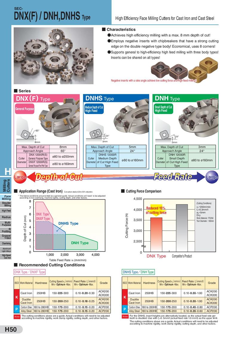
SEC- DNX(F) / DNH,DNHS Type High Efficiency Face Milling Cutters for Cast Iron and Cast Steel ■ Characteristics ●Achieves high efficiency milling with a max. 8 mm depth of cut! ●Employs negative inserts with chipbreakers that have a strong cutting edge on the double negative type body! Economical, uses 8 corners! ●Supports general to high-efficiency high feed milling with three body types! Inserts can be shared on all types! Negative inserts with a rake angle achieve low cutting force and high feed milling!! ■ Series DNX(F)Type DNHS Type DNH Type General Purpose Medium Depth of Cut Small Depth of Cut High Feed High Feed 65° 24° 24° 8mm 5mm 3mm Max. Depth of Cut 8mm Max. Depth of Cut 5mm Max. Depth of Cut 3mm Approach Angle 65° Approach Angle 24° Approach Angle 24° DNX 12000R(S) ø80 to ø250mm DNHS 12000R DNH 12000R Cutter General Purpose Type Cutter Medium Depth ø80 to ø160mm Cutter Small Depth ø80 to ø160mm Diameter DNXF 12000R(S) ø80 to ø160mm Diameter of Cut High Feed Diameter of Cut High Feed General Purpose Fine Pitch Type Type Type H Large Large Milling Cutters ■ Application Range (Cast Iron) Cut carbon steel at 20 to 30% reduction. ■ Cutting Force Comparison Face * The below conditions are provided as a general guide. Actual conditions will need to be adjusted Milling according to tool overhang, machine rigidity, cutting depth, and other factors. 4,500 Shoulder (Cutting Conditions) Milling Reduced 15% vc=200m/min High Feed 4,000 fz=0.3mm/t DNX Type Cutting Force (N) of cutting force ap=5mm Radius Depth of Cut (mm) Dry DNXF Type 3,500 Work Material : FC250 Multi- DNHS Type Tool Diameter : 100mm Purpose R/ 3,000 Profiling Groove/ T-Slot Chamfering DNH Type 2,500 Aluminum/ Light Alloys 0 High-Speed DNX Type Competitor's Product Cast Iron Table Feed Rate vf (mm/min) ■ Recommended Cutting Conditions DNX Type/DNXF Type DNHS Type/DNH Type ISO Work Material Hardness Cutting Speed v(c m/min) Feed Rate f(z mm/t) Grade ISO Work Material Hardness Cutting Speed v(c m/min) Feed Rate f(z mm/t) Grade Min.- Optimum -Max. Min.- Optimum -Max. Min.- Optimum -Max. Min.- Optimum -Max. Cast Iron 250HB 150- 225 -300 0.10- 0.20 -0.30 ACK200 Cast Iron 250HB 150- 225 -300 0.10- 0.55 -1.00 ACK200 K ACK300 K ACK300 Ductile 250HB 150-200-250 0.10- 0.18 -0.25 ACK200 Ductile 250HB 150-200-250 0.10- 0.55 -1.00 ACK200 Cast Iron ACK300 Cast Iron ACK300 P Carbon Stee 180 to 280HB 150- 175 -200 0.10- 0.15 -0.20 ACP200 P Carbon Stee 180 to 280HB 150- 175 -200 0.10- 0.45 -0.80 ACP200 Alloy Steel 180 to 280HB 150- 175 -200 0.10- 0.15 -0.20 ACP200 Alloy Steel 180 to 280HB 150- 175 -200 0.10- 0.35 -0.60 ACP200 Note The cutting conditions above are a guide. Actual conditions will need to be adjusted Note For the DNHS, insert heights are alternatively located, so the actual feed rate per according to machine rigidity, work clamp rigidity, cutting depth, and other factors. tooth is doubled. Use with fz=0.5mm/t (actual feed rate 1.0 mm/t) as the upper limit. The cutting conditions above are a guide. Actual conditions will need to be adjusted according to machine rigidity, work clamp rigidity, cutting depth, and other factors. H50