Каталог Sumitomo фрезы со сменными пластинами - страница 15
Навигация
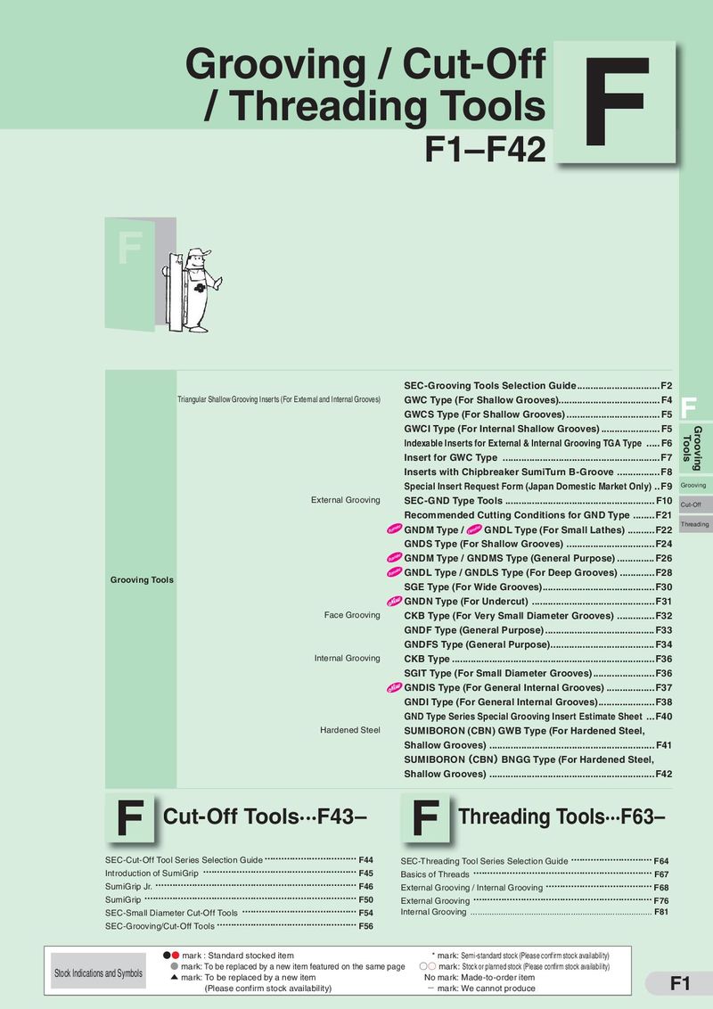 Каталог Sumitomo инструмент для обработки канавок
 Общий каталог Sumitomo 2019 - 2020
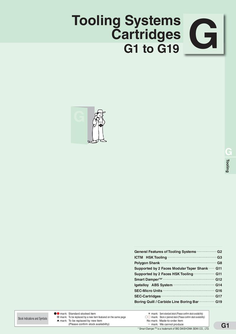 Каталог Sumitomo модульные системы для револьверных головок токарных станков
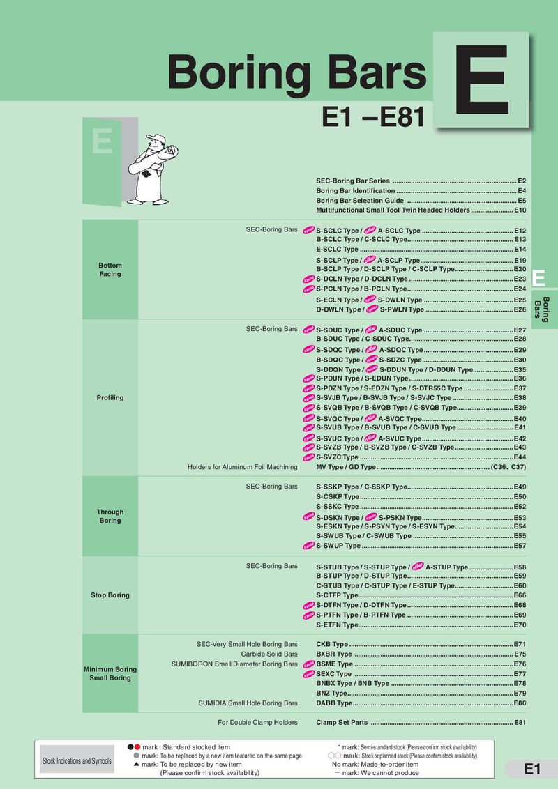 Каталог Sumitomo токарные резцы (державки) для внутреннего точения
 Общий каталог Sumitomo 2018 - 2019
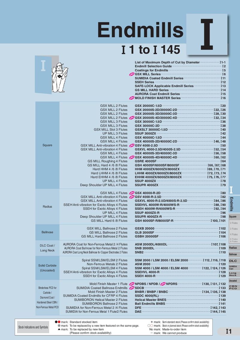 Каталог Sumitomo монолитные фрезы
- H001
- H002
- H003
- H004
- H005
- H006
- H007
- H008
- H009
- H010
- H011
- H012
- H013
- H014
- H015
- H016
- H017
- H018
- H019
- H020
- H021
- H022
- H023
- H024
- H025
- H026
- H027
- H028
- H029
- H030
- H031
- H032
- H033
- H034
- H035
- H036
- H037
- H038
- H039
- H040
- H041
- H042
- H043
- H044
- H045
- H046
- H047
- H048
- H049
- H050
- H051
- H052
- H053
- H054
- H055
- H056
- H057
- H058
- H059
- H060
- H061
- H062
- H063
- H064
- H065
- H066
- H067
- H068
- H069
- H070
- H071
- H072
- H073
- H074
- H075
- H076
- H077
- H078
- H079
- H080
- H081
- H082
- H083
- H084
- H085
- H086
- H087
- H088
- H089
- H090
- H091
- H092
- H093
- H094
- H095
- H096
- H097
- H098
- H099
- H100
- H101
- H102
- H103
- H104
- H105
- H106
- H107
- H108
- H109
- H110
- H111
- H112
- H113
- H114
- H115
- H116
- H117
- H118
- H119
- H120
- H121
- H122
- H123
- H124
- H125
- H126
- H127
- H128
- H129
- H130
- H131
- H132
- H133
- H134
- H135
- H136
- H137
- H138
- H139
- H140
- H141
- H142
- H143
- H144
- H145
- H146
- H147
- H148
- H149
- H150
- H151
- H152
- H153
- H154
- H155
- H156
- H157
- H158
- H159
- H160
- H161
- H162
- H163
- H164
- H165
- H166
- H167
- H168
- H169
- H170
- H171
- H172
- H173
- H174
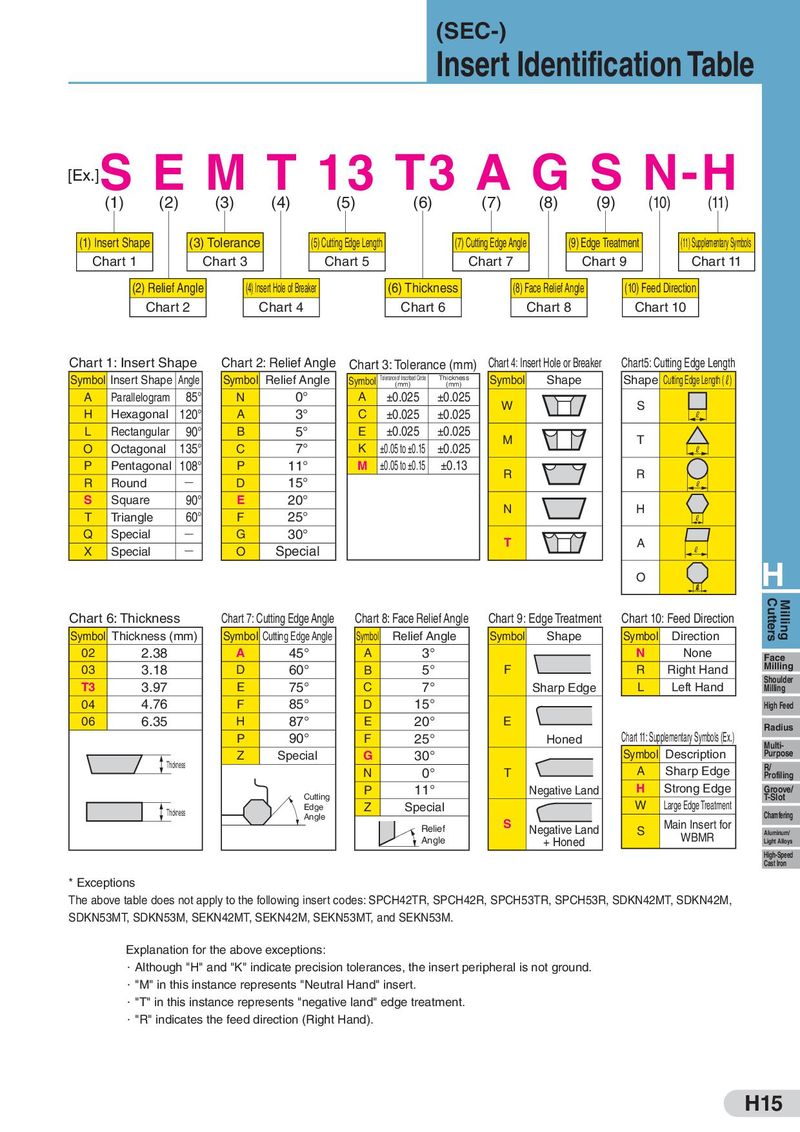
(SEC-) Insert Identification Table S [Ex.] E M T 13 T3 A G S N-H (1) (2) (3) (4) (5) (6) (7) (8) (9) (10) (11) (1) Insert Shape (3) Tolerance (5) Cutting Edge Length (7) Cutting Edge Angle (9) Edge Treatment (11) Supplementary Symbols Chart 1 Chart 3 Chart 5 Chart 7 Chart 9 Chart 11 (2) Relief Angle (4) Insert Hole of Breaker (6) Thickness (8) Face Relief Angle (10) Feed Direction Chart 2 Chart 4 Chart 6 Chart 8 Chart 10 Chart 1: Insert Shape Chart 2: Relief Angle Chart 3: Tolerance (mm) Chart 4: Insert Hole or Breaker Chart5: Cutting Edge Length Symbol Insert Shape Angle Symbol Relief Angle Symbol Tolerance of Inscribed Circle Thickness Symbol Shape Shape Cutting Edge Length (L) (mm) (mm) A Parallelogram 85° N 0° A ±0.025 ±0.025 W S H Hexagonal 120° A 3° C ±0.025 ±0.025 L L Rectangular 90° B 5° E ±0.025 ±0.025 M T O Octagonal 135° C 7° K ±0.05 to ±0.15 ±0.025 L P Pentagonal 108° P 11° M ±0.05 to ±0.15 ±0.13 R R R Round Q D 15° L S Square 90° E 20° N H T Triangle 60° F 25° L Q Special Q G 30° T A X Special Q O Special L O H Chart 6: Thickness Chart 7: Cutting Edge Angle Chart 8: Face Relief Angle Chart 9: Edge Treatment Chart 10: Feed Direction Cutters Milling Symbol Thickness (mm) Symbol Cutting Edge Angle Symbol Relief Angle Symbol Shape Symbol Direction 02 2.38 A 45° A 3° N None Face 03 3.18 D 60° B 5° F R Right Hand Milling T3 3.97 E 75° C 7° Sharp Edge L Left Hand Shoulder Milling 04 4.76 F 85° D 15° High Feed 06 6.35 H 87° E 20° E Radius P 90° F 25° Honed Chart 11: Supplementary Symbols (Ex.) Multi- Z Special G 30° Symbol Description Purpose Thickness N 0° T A Sharp Edge R/ Profiling Cutting P 11° Negative Land H Strong Edge Groove/ T-Slot W Large Edge Treatment Thickness Edge Z Special Angle S Main Insert for Chamfering Relief Negative Land S WBMR Aluminum/ Angle + Honed Light Alloys High-Speed Cast Iron * Exceptions The above table does not apply to the following insert codes: SPCH42TR, SPCH42R, SPCH53TR, SPCH53R, SDKN42MT, SDKN42M, SDKN53MT, SDKN53M, SEKN42MT, SEKN42M, SEKN53MT, and SEKN53M. Explanation for the above exceptions: ・Although "H" and "K" indicate precision tolerances, the insert peripheral is not ground. ・"M" in this instance represents "Neutral Hand" insert. ・"T" in this instance represents "negative land" edge treatment. ・"R" indicates the feed direction (Right Hand). H15