Каталог Sumitomo фрезы со сменными пластинами - страница 138
Навигация
 Каталог Sumitomo инструмент для обработки канавок
 Общий каталог Sumitomo 2019 - 2020
 Каталог Sumitomo модульные системы для револьверных головок токарных станков
 Каталог Sumitomo токарные резцы (державки) для внутреннего точения
 Общий каталог Sumitomo 2018 - 2019
 Каталог Sumitomo монолитные фрезы
- H001
- H002
- H003
- H004
- H005
- H006
- H007
- H008
- H009
- H010
- H011
- H012
- H013
- H014
- H015
- H016
- H017
- H018
- H019
- H020
- H021
- H022
- H023
- H024
- H025
- H026
- H027
- H028
- H029
- H030
- H031
- H032
- H033
- H034
- H035
- H036
- H037
- H038
- H039
- H040
- H041
- H042
- H043
- H044
- H045
- H046
- H047
- H048
- H049
- H050
- H051
- H052
- H053
- H054
- H055
- H056
- H057
- H058
- H059
- H060
- H061
- H062
- H063
- H064
- H065
- H066
- H067
- H068
- H069
- H070
- H071
- H072
- H073
- H074
- H075
- H076
- H077
- H078
- H079
- H080
- H081
- H082
- H083
- H084
- H085
- H086
- H087
- H088
- H089
- H090
- H091
- H092
- H093
- H094
- H095
- H096
- H097
- H098
- H099
- H100
- H101
- H102
- H103
- H104
- H105
- H106
- H107
- H108
- H109
- H110
- H111
- H112
- H113
- H114
- H115
- H116
- H117
- H118
- H119
- H120
- H121
- H122
- H123
- H124
- H125
- H126
- H127
- H128
- H129
- H130
- H131
- H132
- H133
- H134
- H135
- H136
- H137
- H138
- H139
- H140
- H141
- H142
- H143
- H144
- H145
- H146
- H147
- H148
- H149
- H150
- H151
- H152
- H153
- H154
- H155
- H156
- H157
- H158
- H159
- H160
- H161
- H162
- H163
- H164
- H165
- H166
- H167
- H168
- H169
- H170
- H171
- H172
- H173
- H174
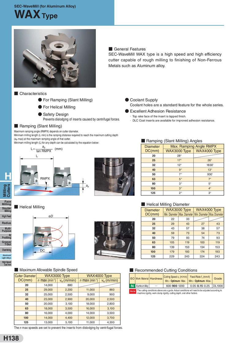
SEC-WaveMill (for Aluminum Alloy)
WAX
- General Features
SEC-WaveMill WAX type is a high speed and high efficiency
cutter capable of rough milling to finishing of Non-Ferrous
Metals such as Aluminum alloy.
- Characteristics
- For Ramping (Slant Milling)
- Coolant Supply
- Coolant holes are a standard feature for the whole series.
For Helical Milling
- Excellent Adhesion Resistance
- Safety Design
- Top rake face of the insert is lapped finish.
Prevents dislodging of inserts caused by centrifugal forces.
- DLC Coat inserts are available for improved adhesion resistance.
- Ramping (Slant Milling)
Maximum ramping angle (RMPX) depends on cutter diameter. Minimum milling length (L min) is the ramping distance required to reach the maximum cutting depth (ap max) at the maximum ramping angle of that cutter. Ramping (Slant Milling) Angles Minimum milling length (L) for any depth can be calculated by the equation below:
a Diameter Max. Ramping Angle RMPX
L = p (mm)
tan RMPX DC(mm) WAX3000 Type WAX4000 Type
| L 20 | 28° | |
| 25 | 17° | 26° |
| 32 | 12° | 1830’ |
| 40 | 9° | 13° |
| H 50 | 7° | 930’ |
| RMPX 63 | 5° | 7° |
| 80 | 3° | 5° |
| a | ||
| p | ||
| 100 | 3° | 4° |
| 125 | 2° | 3° |
| ■ Face |
Milling Helical Milling Diameter
Helical Milling
| Diameter | WAX30 | 00 Type | WAX40 | 00 Type |
| DC(mm) | Min. Diameter | Max. Diameter | Min. Diameter | Max. Diameter |
| 20 | 22 | 33 | ||
| 25 | 29 | 43 | 27 | 43 |
| 32 | 43 | 57 | 38 | 57 |
| 40 | 59 | 73 | 54 | 73 |
| 50 | 79 | 93 | 74 | 93 |
| 63 | 105 | 119 | 100 | 119 |
| 80 | 139 | 153 | 134 | 153 |
| 100 | 179 | 193 | 174 | 193 |
| 125 | 229 | 243 | 224 | 243 |
Milling High Feed øD
Purpose R/
T-Slot Chamfering DC
Light Alloys High-Speed Cast Iron
- Maximum Allowable Spindle Speed
Recommended Cutting Conditions
| Cutter Diameter | WAX30 | 00 Type | WAX40 | 00 Type |
| DC(mm) | nmax (min-1) | vc(m/min) | nmax (min-1) | vc(m/min) |
| 20 | 14,000 | 880 | ||
| 25 | 29,000 | 2,200 | 11,000 | 860 |
| 32 | 25,000 | 2,500 | 9,000 | 900 |
| 40 | 23,000 | 2,900 | 20,000 | 2,500 |
| 50 | 20,000 | 3,100 | 18,000 | 2,800 |
| 63 | 18,000 | 3,500 | 16,000 | 3,100 |
| 80 | 16,000 | 4,000 | 14,000 | 3,500 |
| 100 | 14,000 | 4,400 | 12,000 | 3,700 |
| 125 | 13,000 | 5,100 | 11,000 | 4,300 |
Cutting Speed v (m/min) Feed Rate f (mm/t)
Note
The n max speeds are set to prevent the inserts from dislodging by centrifugal forces.