Каталог Sumitomo фрезы со сменными пластинами - страница 65
Навигация
 Каталог Sumitomo инструмент для обработки канавок
 Общий каталог Sumitomo 2019 - 2020
 Каталог Sumitomo модульные системы для револьверных головок токарных станков
 Каталог Sumitomo токарные резцы (державки) для внутреннего точения
 Общий каталог Sumitomo 2018 - 2019
 Каталог Sumitomo монолитные фрезы
- H001
- H002
- H003
- H004
- H005
- H006
- H007
- H008
- H009
- H010
- H011
- H012
- H013
- H014
- H015
- H016
- H017
- H018
- H019
- H020
- H021
- H022
- H023
- H024
- H025
- H026
- H027
- H028
- H029
- H030
- H031
- H032
- H033
- H034
- H035
- H036
- H037
- H038
- H039
- H040
- H041
- H042
- H043
- H044
- H045
- H046
- H047
- H048
- H049
- H050
- H051
- H052
- H053
- H054
- H055
- H056
- H057
- H058
- H059
- H060
- H061
- H062
- H063
- H064
- H065
- H066
- H067
- H068
- H069
- H070
- H071
- H072
- H073
- H074
- H075
- H076
- H077
- H078
- H079
- H080
- H081
- H082
- H083
- H084
- H085
- H086
- H087
- H088
- H089
- H090
- H091
- H092
- H093
- H094
- H095
- H096
- H097
- H098
- H099
- H100
- H101
- H102
- H103
- H104
- H105
- H106
- H107
- H108
- H109
- H110
- H111
- H112
- H113
- H114
- H115
- H116
- H117
- H118
- H119
- H120
- H121
- H122
- H123
- H124
- H125
- H126
- H127
- H128
- H129
- H130
- H131
- H132
- H133
- H134
- H135
- H136
- H137
- H138
- H139
- H140
- H141
- H142
- H143
- H144
- H145
- H146
- H147
- H148
- H149
- H150
- H151
- H152
- H153
- H154
- H155
- H156
- H157
- H158
- H159
- H160
- H161
- H162
- H163
- H164
- H165
- H166
- H167
- H168
- H169
- H170
- H171
- H172
- H173
- H174
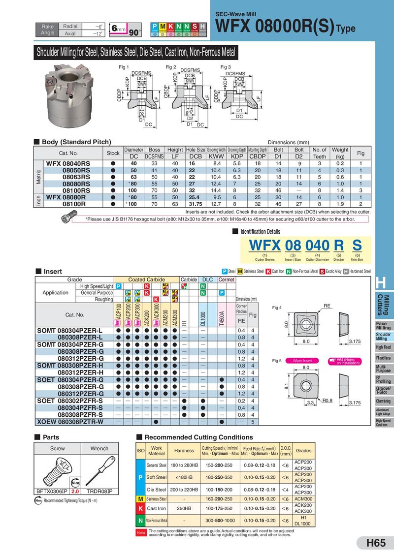
SEC-Wave Mill Rake Radial −6° 6mm P MKNN SH WFX 08000R(S)Type Angle Axial 90° Steel Stainless Steel Cast Iron Non-Ferrous Metal Aluminum Exotic Alloy Hardened Steel −12° G G G G G S Shoulder Milling for Steel, Stainless Steel, Die Steel, Cast Iron, Non-Ferrous Metal Fig 1 Fig 2 DCSFMS Fig 3 DCSFMS KDP DCB DCSFMS KDP DCB KWW KDP DCB KWW CBDP KWW CBDP LF LF CBDP LF D2 ø17 D1 D1 D2 DC DC D1 DC ■ Body (Standard Pitch) Dimensions (mm) Cat. No. Stock Diameter Boss Height Hole Size Grooving Width Grooving Depth Mounting Depth Bolt Bolt No. of Weight Fig DC DCSFMS LF DCB KWW KDP CBDP D1 D2 Teeth (kg) WFX 08040RS D 40 33 40 16 8.4 5.6 18 14 9 3 0.2 1 Metric 08050RS D 50 41 40 22 10.4 6.3 20 18 11 4 0.3 1 08063RS D 63 50 40 22 10.4 6.3 20 18 11 5 0.6 1 08080RS D *80 55 50 27 12.4 7 25 20 14 6 1.0 1 08100RS D 100 70 50 32 14.4 8 32 46 Q 8 1.4 3 Inch WFX 08080R D *80 55 50 25.4 9.5 6 25 20 14 6 1.0 1 08100R D *100 70 63 31.75 12.7 8 32 46 27 8 1.9 2 Inserts are not included. Check the arbor attachment size (DCB) when selecting the cutter. *Please use JIS B1176 hexagonal bolt (ø80: M12x30 to 35mm, ø100: M16x40 to 45mm) for securing ø80/ø100 cutter to the arbor. ■ Identification Details WFX 08 040 R S (1) (3) (4) (5) (6) Cutter Series Insert Size Cutter Diameter Direction Metric Bore ■ Insert P Steel M Stainless Steel K Cast Iron N Non-Ferrous Metal S Exotic Alloy H Hardened Steel Grade Coated Carbide Carbide DLC Cermet H High Speed/Light P K N Application General Purpose K N P Cutters Milling Roughing K Dimensions (mm) ACP100 ACP200 ACP300 ACK300 Corner Fig 4 RE Cat. No. ACK200 ACM200 ACM300 DL1000 T4500A Radius Fig H1 RE 8.0 Face SOMT 080304PZER-L D D D D D D D Q Q 0.4 4 Milling 080308PZER-L D D D D D D D Q Q 0.8 4 Shoulder Milling 8.0 3.175 SOMT 080304PZER-G D D D D D D D Q Q 0.4 4 High Feed 080308PZER-G 0.8 4 D D D D D D D Q Q 080312PZER-G D D D D D D D Q Q 1.2 4 Fig 5 Wiper Insert H64 (Notes Radius SOMT 080308PZER-H D D D D D D D Q Q 0.8 4 on Installation) 8.0 Multi- Purpose 080312PZER-H D D D D D D D Q Q 1.2 4 SOET 080304PZER-G D D D D D D D Q Q D 0.4 4 R/ Profiling 8.1 080308PZER-G D D D D D D D Q Q D 0.8 4 Groove/ 080312PZER-G D D D D D D D Q Q D 1.2 4 T-Slot SOET 080302PZFR-S Q Q Q Q Q Q Q D D Q 0.2 4 3.3 R0.8 3.175 Chamfering 080304PZFR-S Q Q Q Q Q Q Q D D Q 0.4 4 Aluminum/ 080308PZFR-S Q Q Q Q Q Q Q D D Q 0.8 4 Light Alloys XOEW 080308PZTR-W Q Q Q D Q Q D Q 5 High-Speed Cast Iron ■ Parts ■ Recommended Cutting Conditions Screw Wrench ISO Work Hardness Cutting Speed (c m/min) Feed Rate (z mm/t) D.O.C. Grades Material Min. - Optimum - Max Min. - Optimum - Max(mm) General Steel 180 to 280HB 150-200-250 0.08- 0.12 -0.18 <6 ACP200 ACP300 P Soft Steel ≤180HB 180- 250 -350 0.10- 0.15 -0.20 <6 ACP200 Nm ACP300 Die Steel 200 to 220HB 100- 150 -200 0.08- 0.12 -0.18 <4 ACP200 BFTX0306IP 2.0 TRDR08IP ACP300 N m Recommended Tightening Torque (N・m) M Stainless Steel - 160-200-250 0.10- 0.15 -0.20 <6 ACM300 K Cast Iron 250HB 100- 175 -250 0.10- 0.15 -0.20 <6 ACK200 ACK300 N Non-Ferrous Metal - 300-500-1000 0.10- 0.15 -0.20 <6 H1 DL1000 Note The cutting conditions above are a guide. Actual conditions will need to be adjusted according to machine rigidity, work clamp rigidity, cutting depth, and other factors. H65