Каталог Sumitomo фрезы со сменными пластинами - страница 114
Навигация
 Каталог Sumitomo инструмент для обработки канавок
 Общий каталог Sumitomo 2019 - 2020
 Каталог Sumitomo модульные системы для револьверных головок токарных станков
 Каталог Sumitomo токарные резцы (державки) для внутреннего точения
 Общий каталог Sumitomo 2018 - 2019
 Каталог Sumitomo монолитные фрезы
- H001
- H002
- H003
- H004
- H005
- H006
- H007
- H008
- H009
- H010
- H011
- H012
- H013
- H014
- H015
- H016
- H017
- H018
- H019
- H020
- H021
- H022
- H023
- H024
- H025
- H026
- H027
- H028
- H029
- H030
- H031
- H032
- H033
- H034
- H035
- H036
- H037
- H038
- H039
- H040
- H041
- H042
- H043
- H044
- H045
- H046
- H047
- H048
- H049
- H050
- H051
- H052
- H053
- H054
- H055
- H056
- H057
- H058
- H059
- H060
- H061
- H062
- H063
- H064
- H065
- H066
- H067
- H068
- H069
- H070
- H071
- H072
- H073
- H074
- H075
- H076
- H077
- H078
- H079
- H080
- H081
- H082
- H083
- H084
- H085
- H086
- H087
- H088
- H089
- H090
- H091
- H092
- H093
- H094
- H095
- H096
- H097
- H098
- H099
- H100
- H101
- H102
- H103
- H104
- H105
- H106
- H107
- H108
- H109
- H110
- H111
- H112
- H113
- H114
- H115
- H116
- H117
- H118
- H119
- H120
- H121
- H122
- H123
- H124
- H125
- H126
- H127
- H128
- H129
- H130
- H131
- H132
- H133
- H134
- H135
- H136
- H137
- H138
- H139
- H140
- H141
- H142
- H143
- H144
- H145
- H146
- H147
- H148
- H149
- H150
- H151
- H152
- H153
- H154
- H155
- H156
- H157
- H158
- H159
- H160
- H161
- H162
- H163
- H164
- H165
- H166
- H167
- H168
- H169
- H170
- H171
- H172
- H173
- H174
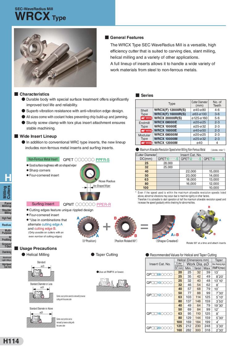
SEC-WaveRadius Mill WRCX Type ■ General Features The WRCX Type SEC WaveRadius Mill is a versatile, high efficiency cutter that is suited to carving dies, slant milling, helical milling and a variety of other applications. A full lineup of inserts allows it to handle a wide variety of work materials from steel to non-ferrous metals. ■ Characteristics ■ Series ● Durable body with special surface treatment offers significantly Cutter Diameter No. of improved tool life and reliability. Type (mm) Teeth ● Superb vibration resistance with anti-vibration edge design. Shell WRCX(F) 12000R(S) ø40-ø80 4-6 ● All sizes come with coolant holes preventing chip build-up and jamming. Type WRCX(F) 16000R(S) ø63-ø100 3-6 H115 WRCX 20000R(S) ø125-ø160 5-6 ● Sturdy screw clamp with torx plus insert attachment ensures Endmill WRCX 08000E ø20-ø25 2-3 stable machining. Type WRCX 10000E ø25-ø32 2-3 H118 WRCX 16000E ø40-ø50 2-3 ■ Wide Insert Lineup Modular WRCX 08000M ø20-ø25 2-3 Type WRCX 10000M ø25-ø32 2-3 ● In addition to conventional WRC type inserts, the new lineup H155 WRCX 12000M ø40 4 includes non-ferrous metal inserts and surfing inserts. ● Maximum Allowable Revolution Speed when Milling Non-Ferrous Metal (Units: min-1) Cutter Diameter Insert Cat. No. Non-Ferrous Metal Insert QPET ○○○○○○ PPFR-S DC(mm) QPET10・・・・-S QPET12・・・・-S QPET16・・・・-S ● Good surface roughness with arc-shaped wiper 25 28,000 ● Sharp corners 32 25,000 40 22,000 15,000 H ● Four-cornered insert 50 20,000 14,000 Nose Radius 63 18,000 13,000 Arc-Shaped Wiper 80 16,000 12,000 Milling Cutters 100 10,000 * Even if the speed used is within the maximum allowable revolution speeds listed above, abnormal vibrations may occur due to machine rigidity or other factors. Therefore it is advisable to start operation at half the maximum allowable revolution speed and Face Surfing Insert QPMT ○○○○○○ PPER-R increase the speed gradually while checking for abnormalities. Milling B Shoulder ● Cutting edges feature unique rippled design Milling ● Four-cornered insert A High Feed ● *Use in combinations that A B A Radius alternate cutting edge A Multi- and cutting edge B. B Purpose (Only useable on cutters with an A+B B R/ even number of cutting edges) A B A Profiling (0°Position) (Position Rotated 90°) (Shape Created) Groove/ Rotate 90° at a time and attach inserts T-Slot ■ Usage Precautions Chamfering ● Helical Milling ● Taper Cutting ● Recommended Values for Helical and Taper Cutting Aluminum/ Helical (Dimensions mm) Taper Light Alloys Standard High-Speed Insert Cat. No. Cutter Work Dia. øD Max. Ramping Angle Diameter Cast Iron øD DC (mm) Min. Standard Max. RMPX(max) ●Use at RMPX or lower. QP□□08○○○○ 20 25 32 39 13˚ 25 35 42 49 8˚20' RMPX QP□□10○○○○ 25 32 40 48 13˚10' Standard Diameter or Less 32 46 54 62 8˚ øD 40 57 68 79 10˚ QP□□12○○○○ 50 77 88 99 7˚30' Center uncut portion cannot be removed by traverse 63 103 114 125 5˚10' cutting with the same cutter 80 137 148 159 3˚50' 40 49 64 79 19˚30' Standard Diameter or Above 50 69 84 99 12˚ øD QP□□16○○○○ 63 95 110 125 8˚ Center uncut portion can be 80 129 144 159 5˚30' removed by traverse cutting with 100 169 184 199 4˚ the same cutter QP□□20○○○○ 125 212 230 248 3˚30' 160 282 300 318 2˚30' H114