Каталог Sumitomo фрезы со сменными пластинами - страница 64
Навигация
 Каталог Sumitomo инструмент для обработки канавок
 Общий каталог Sumitomo 2019 - 2020
 Каталог Sumitomo модульные системы для револьверных головок токарных станков
 Каталог Sumitomo токарные резцы (державки) для внутреннего точения
 Общий каталог Sumitomo 2018 - 2019
 Каталог Sumitomo монолитные фрезы
- H001
- H002
- H003
- H004
- H005
- H006
- H007
- H008
- H009
- H010
- H011
- H012
- H013
- H014
- H015
- H016
- H017
- H018
- H019
- H020
- H021
- H022
- H023
- H024
- H025
- H026
- H027
- H028
- H029
- H030
- H031
- H032
- H033
- H034
- H035
- H036
- H037
- H038
- H039
- H040
- H041
- H042
- H043
- H044
- H045
- H046
- H047
- H048
- H049
- H050
- H051
- H052
- H053
- H054
- H055
- H056
- H057
- H058
- H059
- H060
- H061
- H062
- H063
- H064
- H065
- H066
- H067
- H068
- H069
- H070
- H071
- H072
- H073
- H074
- H075
- H076
- H077
- H078
- H079
- H080
- H081
- H082
- H083
- H084
- H085
- H086
- H087
- H088
- H089
- H090
- H091
- H092
- H093
- H094
- H095
- H096
- H097
- H098
- H099
- H100
- H101
- H102
- H103
- H104
- H105
- H106
- H107
- H108
- H109
- H110
- H111
- H112
- H113
- H114
- H115
- H116
- H117
- H118
- H119
- H120
- H121
- H122
- H123
- H124
- H125
- H126
- H127
- H128
- H129
- H130
- H131
- H132
- H133
- H134
- H135
- H136
- H137
- H138
- H139
- H140
- H141
- H142
- H143
- H144
- H145
- H146
- H147
- H148
- H149
- H150
- H151
- H152
- H153
- H154
- H155
- H156
- H157
- H158
- H159
- H160
- H161
- H162
- H163
- H164
- H165
- H166
- H167
- H168
- H169
- H170
- H171
- H172
- H173
- H174
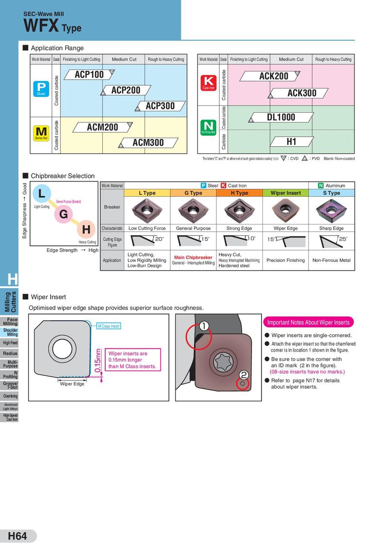
- Application Range
Work Material Grade Finishing to Light Cutting Medium Cut Rough to Heavy Cutting Work Material Grade Finishing to Light Cutting Medium Cut Rough to Heavy Cutting
ACP100 C ACK200 C
K P ACP200 Cast Iron ACK300 Steel P
P
ACP300
P
DL1000
N P
| M | ACM200 | C | |||
| Non-Ferrous Metal | |||||
| Stainless Steel | ACM300 | H1 | |||
| P |
The letters "C" and "P" at either end of each grade indicate coating type. C:CVD :PVD Blank: Non-coated
P
- Chipbreaker Selection
| Work Material | P Steel | K Cast Iron | N | Aluminum | |||
| L | |||||||
| G Type L Type | H Type | Wiper Insert | S Type | ||||
| General Purpose (Standard) | |||||||
| Light Cutting | Breaker | ||||||
| G | |||||||
| H Characteristic | General Purpose Low Cutting Force | Strong Edge | Wiper Edge | Sharp Edge | |||
| 20° 15° | 15° 10° | 25° |
Cutting Edge Heavy Cutting Figure Edge Strength → High
Light Cutting, Heavy Cut, Main Chipbreaker
Application Low Rigidity Milling Heavy Interrupted Machining Precision Finishing Non-Ferrous Metal
General - Interrupted Milling Low-Burr Design Hardened steel H
- Wiper Insert Optimised wiper edge shape provides superior surface roughness.
Face Important Notes About Wiper Inserts Milling M Class Insert Shoulder Milling Wiper inserts are single-cornered. High Feed Attach the wiper insert so that the chamfered corner is in location 1 shown in the figure. Radius Wiper inserts are
- Be sure to use the corner with
0.15mm longer
Multi-
Purpose than M Class inserts. an ID mark (2 in the figure).
R/ (08-size inserts have no marks.) Profiling Refer to page N17 for details Groove/ Wiper Edge
T-Slot about wiper inserts. Chamfering Aluminum/ Light Alloys High-Speed Cast Iron