Каталог Sumitomo фрезы со сменными пластинами - страница 9
Навигация
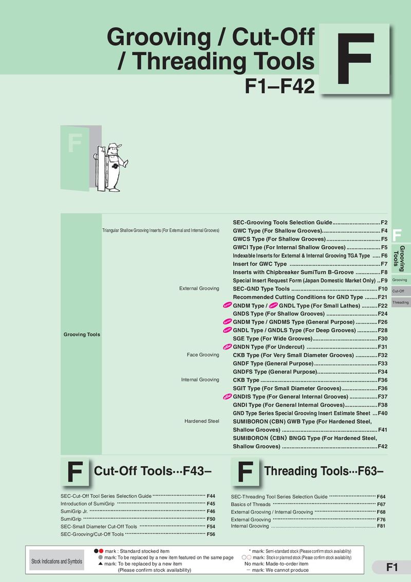 Каталог Sumitomo инструмент для обработки канавок
 Общий каталог Sumitomo 2019 - 2020
 Каталог Sumitomo модульные системы для револьверных головок токарных станков
 Каталог Sumitomo токарные резцы (державки) для внутреннего точения
 Общий каталог Sumitomo 2018 - 2019
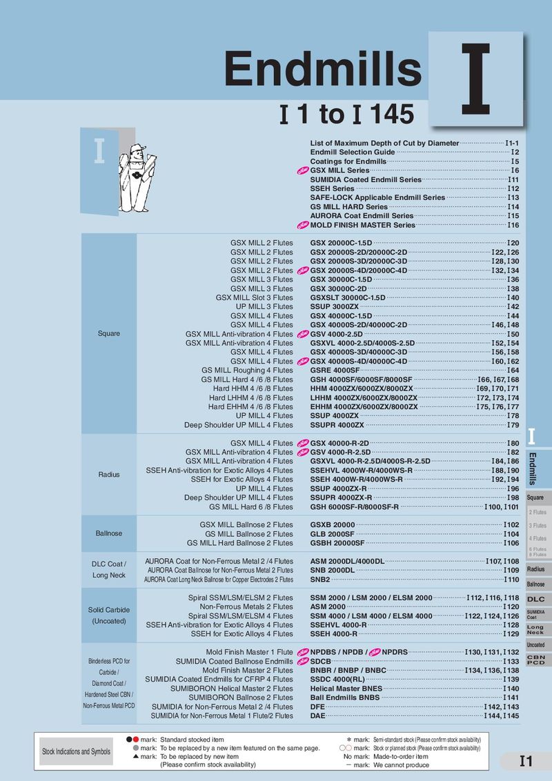 Каталог Sumitomo монолитные фрезы
- H001
- H002
- H003
- H004
- H005
- H006
- H007
- H008
- H009
- H010
- H011
- H012
- H013
- H014
- H015
- H016
- H017
- H018
- H019
- H020
- H021
- H022
- H023
- H024
- H025
- H026
- H027
- H028
- H029
- H030
- H031
- H032
- H033
- H034
- H035
- H036
- H037
- H038
- H039
- H040
- H041
- H042
- H043
- H044
- H045
- H046
- H047
- H048
- H049
- H050
- H051
- H052
- H053
- H054
- H055
- H056
- H057
- H058
- H059
- H060
- H061
- H062
- H063
- H064
- H065
- H066
- H067
- H068
- H069
- H070
- H071
- H072
- H073
- H074
- H075
- H076
- H077
- H078
- H079
- H080
- H081
- H082
- H083
- H084
- H085
- H086
- H087
- H088
- H089
- H090
- H091
- H092
- H093
- H094
- H095
- H096
- H097
- H098
- H099
- H100
- H101
- H102
- H103
- H104
- H105
- H106
- H107
- H108
- H109
- H110
- H111
- H112
- H113
- H114
- H115
- H116
- H117
- H118
- H119
- H120
- H121
- H122
- H123
- H124
- H125
- H126
- H127
- H128
- H129
- H130
- H131
- H132
- H133
- H134
- H135
- H136
- H137
- H138
- H139
- H140
- H141
- H142
- H143
- H144
- H145
- H146
- H147
- H148
- H149
- H150
- H151
- H152
- H153
- H154
- H155
- H156
- H157
- H158
- H159
- H160
- H161
- H162
- H163
- H164
- H165
- H166
- H167
- H168
- H169
- H170
- H171
- H172
- H173
- H174
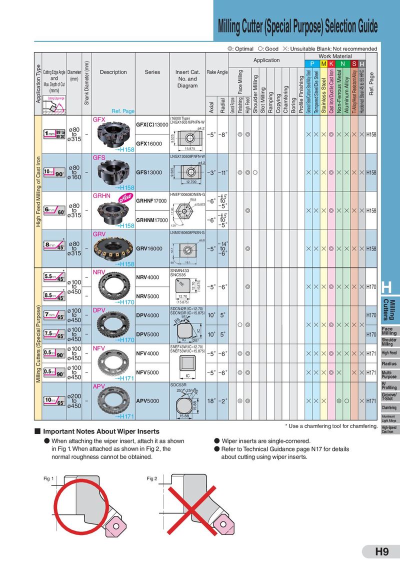
Milling Cutter (Special Purpose) Selection Guide G: Optimal S: Good H: Unsuitable Blank: Not recommended Application Work Material Application Type Shank Diameter (mm) P MK N S H Cutting Edge Angle Diameter Description Series Insert Cat. Rake Angle Face Milling General Steel/Carbon Steel/Alloy Steel Tempered Steel/Die Steel Cast Iron/Ductile Cast Iron Non-Ferrous Metal Ti Alloy/Heat Resistant Alloy Hardened Steel 45 to 55 HRC Ref. Page and (mm) No. and Shoulder Milling Profile Finishing Stainless Steel Aluminum Alloy Max. Depth of Cut Diagram Chamfering (mm) Slot Milling Ramping Cutting Edge Angle Radial General Purpose Finishing High Feed Copying Boring Ref. Page Axial GFX (16000 Type) GFX(C)13000 LNGX160516PNFN-W ø80 ø4.2 1mm 89°to to − −5°−8° G G H H H G H H H H H158 89°30′ ø315 9.525 GFX16000 →H158 15.875 Iron GFS LNGX130508PNFN-W ø4.2 Cast 10mm ø80 9.525 90°ø1to60 − GFS13000 −3°−11° G G S H H H G H H H H H158 of 12.700 Milling →H158 GRHN HNEF100608DNEN-G −6°−t6o.5゚ GRHNF17000 R0.8 Feed ø80 ø15.875 −5° 6mm 60°ø3to15 − 17.00 G H H H G H H H H H158 High GRHNM17000 −6°−t6o.5゚ −5° →H158 120゚ GRV LNMX160608PNSN-G * ø80 ø4.6 8mm 45° to − GRV16000 −5°−t1o4° G H H H G H H H H H158 ø315 12.7 −6° →H158 90˚ 16.1 * NRV SNMN433 5.5mm 45°ø100 − NRV4000 SNC535 to RE 12.70 (15.875) −5°−6° G H H H G H H H H H170 H 8.5mm * ø450 − NRV5000 45° 12.70 →H170 (15.875) Cutters Milling Purpose) ø100 DPV SDCN42R(IC=12.70) 7mm 65°ø4to50 − DPV4000 SDCN53R(IC=15.875) 10° 5° H170 BS 15° ø100 S G H H H G H H H H Face (Special 7.5mm 65°ø4to50 − DPV5000 IC 10° 5° H170 Milling →H170 IC 25° Shoulder NFV SNEF43W(IC=12.70) Milling Cutters 0.5mm ø100 SNEF53W(IC=15.875)−5°−6° 90°ø4to50 − NFV4000 G G H H H G H H H H H171 High Feed ø100 Radius Milling 0.5mm 90°ø4to50 − NFV5000 −5°−6° G G H H H G H H H H171 Multi- →H171 IC Purpose APV SDC53R R/ Profiling 25° 25°BS ø200 Groove/ T-Slot 10mm 65°ø4to50 − APV5000 18°−2° G G H H H G S H H171 15.88 Chamfering →H171 15.88 Aluminum/ Light Alloys ■ Important Notes About Wiper Inserts * Use a chamfering tool for chamfering. High-Speed Cast Iron ● When attaching the wiper insert, attach it as shown ● Wiper inserts are single-cornered. in Fig 1. When attached as shown in Fig 2, the ● Refer to Technical Guidance page N17 for details normal roughness cannot be obtained. about cutting using wiper inserts. Fig 1 Fig 2 H9