Каталог Sumitomo фрезы со сменными пластинами - страница 101
Навигация
 Каталог Sumitomo инструмент для обработки канавок
 Общий каталог Sumitomo 2019 - 2020
 Каталог Sumitomo модульные системы для револьверных головок токарных станков
 Каталог Sumitomo токарные резцы (державки) для внутреннего точения
 Общий каталог Sumitomo 2018 - 2019
 Каталог Sumitomo монолитные фрезы
- H001
- H002
- H003
- H004
- H005
- H006
- H007
- H008
- H009
- H010
- H011
- H012
- H013
- H014
- H015
- H016
- H017
- H018
- H019
- H020
- H021
- H022
- H023
- H024
- H025
- H026
- H027
- H028
- H029
- H030
- H031
- H032
- H033
- H034
- H035
- H036
- H037
- H038
- H039
- H040
- H041
- H042
- H043
- H044
- H045
- H046
- H047
- H048
- H049
- H050
- H051
- H052
- H053
- H054
- H055
- H056
- H057
- H058
- H059
- H060
- H061
- H062
- H063
- H064
- H065
- H066
- H067
- H068
- H069
- H070
- H071
- H072
- H073
- H074
- H075
- H076
- H077
- H078
- H079
- H080
- H081
- H082
- H083
- H084
- H085
- H086
- H087
- H088
- H089
- H090
- H091
- H092
- H093
- H094
- H095
- H096
- H097
- H098
- H099
- H100
- H101
- H102
- H103
- H104
- H105
- H106
- H107
- H108
- H109
- H110
- H111
- H112
- H113
- H114
- H115
- H116
- H117
- H118
- H119
- H120
- H121
- H122
- H123
- H124
- H125
- H126
- H127
- H128
- H129
- H130
- H131
- H132
- H133
- H134
- H135
- H136
- H137
- H138
- H139
- H140
- H141
- H142
- H143
- H144
- H145
- H146
- H147
- H148
- H149
- H150
- H151
- H152
- H153
- H154
- H155
- H156
- H157
- H158
- H159
- H160
- H161
- H162
- H163
- H164
- H165
- H166
- H167
- H168
- H169
- H170
- H171
- H172
- H173
- H174
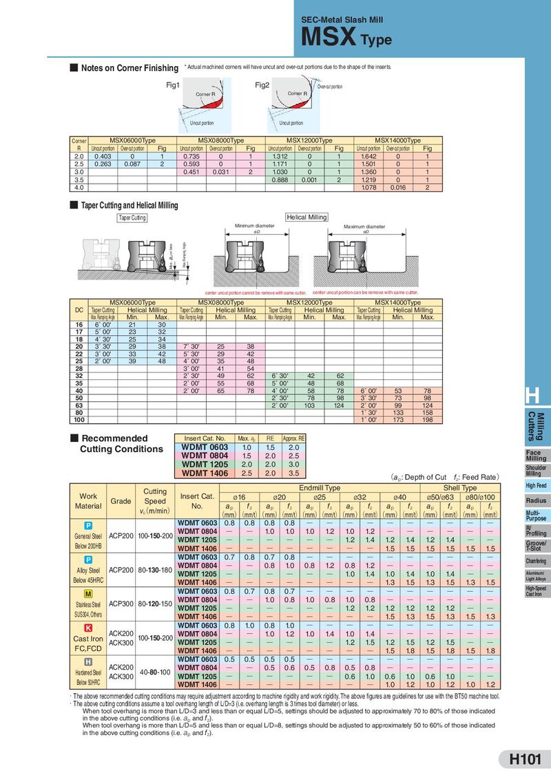
SEC-Metal Slash Mill MSX Type ■ Notes on Corner Finishing * Actual machined corners will have uncut and over-cut portions due to the shape of the inserts. Fig1 Fig2 Over-cut portion Corner R Corner R Uncut portion Uncut portion Corner MSX06000 Type MSX08000 Type MSX12000 Type MSX14000 Type R Uncut portion Over-cut portion Fig Uncut portion Over-cut portion Fig Uncut portion Over-cut portion Fig Uncut portion Over-cut portion Fig 2.0 0.403 0 1 0.735 0 1 1.312 0 1 1.642 0 1 2.5 0.263 0.087 2 0.593 0 1 1.171 0 1 1.501 0 1 3.0 0.451 0.031 2 1.030 0 1 1.360 0 1 3.5 0.888 0.001 2 1.219 0 1 4.0 1.078 0.016 2 ■ Taper Cutting and Helical Milling Taper Cutting Helical Milling Minimum diameter Maximum diameter øD øD Max. a p or less Max. Ramping Angle center uncut portion cannot be remove with same cutter. center uncut portion can be remove with same cutter. MSX06000 Type MSX08000 Type MSX12000 Type MSX14000 Type DC Taper Cutting Helical Milling Taper Cutting Helical Milling Taper Cutting Helical Milling Taper Cutting Helical Milling Max. Ramping Angle Min. Max. Max. Ramping Angle Min. Max. Max. Ramping Angle Min. Max. Max. Ramping Angle Min. Max. 16 6˚ 00' 21 30 17 5˚ 00' 23 32 18 4˚ 30' 25 34 20 3˚ 30' 29 38 7˚ 30' 25 38 22 3˚ 00' 33 42 5˚ 30' 29 42 25 2˚ 00' 39 48 4˚ 00' 35 48 28 3˚ 00' 41 54 32 2˚ 30' 49 62 6˚ 30' 42 62 35 2˚ 00' 55 68 5˚ 00' 48 68 40 2˚ 00' 65 78 4˚ 00' 58 78 6˚ 00' 53 78 H 50 2˚ 30' 78 98 3˚ 30' 73 98 63 2˚ 00' 103 124 2˚ 00' 99 124 80 1˚ 30' 133 158 Cutters Milling 100 1˚ 00' 173 198 ■ Recommended Insert Cat. No. Max. ap RE Approx. RE Cutting Conditions WDMT 0603 1.0 1.5 2.0 Face WDMT 0804 1.5 2.0 2.5 Milling WDMT 1205 2.0 2.0 3.0 Shoulder WDMT 1406 2.5 2.0 3.5 (ap: Depth of Cut fz: Feed Rate) Milling Cutting Endmill Type Shell Type High Feed Work Grade Speed Insert Cat. ø16 ø20 ø25 ø32 ø40 ø50/ø63 ø80/ø100 Radius Material v(c m/min) No. ap fz ap fz ap fz ap fz ap fz ap fz ap fz (mm)(mm/t)(mm)(mm/t)(mm)(mm/t)(mm)(mm/t)(mm)(mm/t)(mm)(mm/t)(mm)(mm/t) Multi- Purpose WDMT 0603 0.8 0.8 0.8 0.8 Q Q Q Q Q Q Q Q Q Q P R/ WDMT 0804 Q Q 1.0 1.0 1.0 1.2 1.0 1.2 Q Q Q Q Q Q General Steel ACP200 100-150-200 Profiling 1.2 1.4 1.2 1.4 1.2 1.4 Below 200HB WDMT 1205 Q Q Q Q Q Q Q Q Groove/ WDMT 1406 Q Q Q Q Q Q Q Q 1.5 1.5 1.5 1.5 1.5 1.5 T-Slot P WDMT 0603 0.7 0.8 0.7 0.8 Q Q Q Q Q Q Q Q Q Q Chamfering Alloy Steel ACP200 80-130-180 WDMT 0804 Q Q 0.8 1.0 0.8 1.2 0.8 1.2 Q Q Q Q Q Q WDMT 1205 Q Q Q Q Q Q 1.0 1.4 1.0 1.4 1.0 1.4 Q Q Aluminum/ Below 45HRC WDMT 1406 Q Q Q Q Q Q Q Q 1.3 1.5 1.3 1.5 1.3 1.5 Light Alloys M WDMT 0603 0.8 0.7 0.8 0.7 Q Q Q Q Q Q Q Q Q Q High-Speed WDMT 0804 1.0 0.8 1.0 0.8 1.0 0.8 Cast Iron Stainless Steel ACP300 80-120-150 Q Q Q Q Q Q Q Q SUS304, Others WDMT 1205 Q Q Q Q Q Q 1.2 1.2 1.2 1.2 1.2 1.2 Q Q WDMT 1406 Q Q Q Q Q Q Q Q 1.5 1.3 1.5 1.3 1.5 1.3 K WDMT 0603 0.8 1.0 0.8 1.0 Q Q Q Q Q Q Q Q Q Q Cast Iron ACK200 100-150-200 WDMT 0804 Q Q 1.0 1.2 1.0 1.4 1.0 1.4 Q Q Q Q Q Q FC,FCD ACK300 WDMT 1205 Q Q Q Q Q Q 1.2 1.5 1.2 1.5 1.2 1.5 Q Q WDMT 1406 Q Q Q Q Q Q Q Q 1.5 1.8 1.5 1.8 1.5 1.8 H WDMT 0603 0.5 0.5 0.5 0.5 Q Q Q Q Q Q Q Q Q Q Hardened Steel ACK200 40-80-100 WDMT 0804 Q Q 0.5 0.6 0.5 0.8 0.5 0.8 Q Q Q Q Q Q Below 50HRC ACK300 WDMT 1205 Q Q Q Q Q Q 0.6 1.0 0.6 1.0 0.6 1.0 Q Q WDMT 1406 Q Q Q Q Q Q Q Q 1.0 1.2 1.0 1.2 1.0 1.2 ・The above recommended cutting conditions may require adjustment according to machine rigidity and work rigidity. The above figures are guidelines for use with the BT50 machine tool. ・The above cutting conditions assume a tool overhang length of L/D=3 (i.e. overhang length is 3 times tool diameter) or less. When tool overhang is more than L/D=3 and less than or equal L/D=5, settings should be adjusted to approximately 70 to 80% of those indicated in the above cutting conditions (i.e. ap and fz). When tool overhang is more than L/D=5 and less than or equal L/D=8, settings should be adjusted to approximately 50 to 60% of those indicated in the above cutting conditions (i.e. ap and fz). H101