Каталог Sumitomo фрезы со сменными пластинами - страница 76
Навигация
 Каталог Sumitomo инструмент для обработки канавок
 Общий каталог Sumitomo 2019 - 2020
 Каталог Sumitomo модульные системы для револьверных головок токарных станков
 Каталог Sumitomo токарные резцы (державки) для внутреннего точения
 Общий каталог Sumitomo 2018 - 2019
 Каталог Sumitomo монолитные фрезы
- H001
- H002
- H003
- H004
- H005
- H006
- H007
- H008
- H009
- H010
- H011
- H012
- H013
- H014
- H015
- H016
- H017
- H018
- H019
- H020
- H021
- H022
- H023
- H024
- H025
- H026
- H027
- H028
- H029
- H030
- H031
- H032
- H033
- H034
- H035
- H036
- H037
- H038
- H039
- H040
- H041
- H042
- H043
- H044
- H045
- H046
- H047
- H048
- H049
- H050
- H051
- H052
- H053
- H054
- H055
- H056
- H057
- H058
- H059
- H060
- H061
- H062
- H063
- H064
- H065
- H066
- H067
- H068
- H069
- H070
- H071
- H072
- H073
- H074
- H075
- H076
- H077
- H078
- H079
- H080
- H081
- H082
- H083
- H084
- H085
- H086
- H087
- H088
- H089
- H090
- H091
- H092
- H093
- H094
- H095
- H096
- H097
- H098
- H099
- H100
- H101
- H102
- H103
- H104
- H105
- H106
- H107
- H108
- H109
- H110
- H111
- H112
- H113
- H114
- H115
- H116
- H117
- H118
- H119
- H120
- H121
- H122
- H123
- H124
- H125
- H126
- H127
- H128
- H129
- H130
- H131
- H132
- H133
- H134
- H135
- H136
- H137
- H138
- H139
- H140
- H141
- H142
- H143
- H144
- H145
- H146
- H147
- H148
- H149
- H150
- H151
- H152
- H153
- H154
- H155
- H156
- H157
- H158
- H159
- H160
- H161
- H162
- H163
- H164
- H165
- H166
- H167
- H168
- H169
- H170
- H171
- H172
- H173
- H174
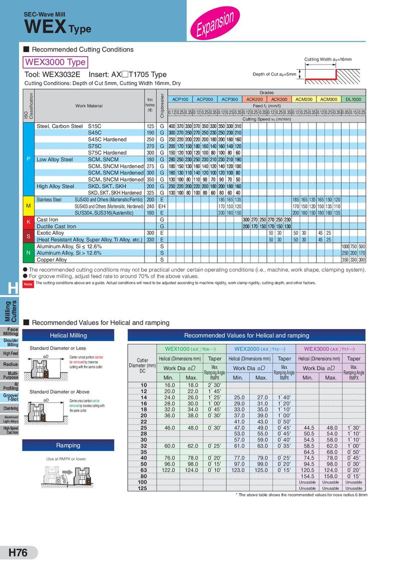
SEC-Wave Mill Expansion WEX Type ■ Recommended Cutting Conditions WEX3000 Type Cutting Width ae=16mm Tool: WEX3032E Insert: AX□T1705 Type Depth of Cut ap=5mm Cutting Conditions: Depth of Cut 5mm, Cutting Width 16mm, Dry Classification Chipbreaker Grades Work ACP100 ACP200 ACP300 ACK200 ACK300 ACM200 ACM300 DL1000 Work Material Hardness Feed fz (mm/t) ISO (HB) 0.12 0.25 0.35 0.12 0.25 0.35 0.12 0.25 0.35 0.12 0.25 0.35 0.12 0.25 0.35 0.12 0.25 0.35 0.12 0.25 0.35 0.05 0.15 0.25 Cutting Speed vc (m/min) Steel, Carbon Steel S15C 125 G 400 370 350 370 350 330 350 330 310 S45C 190 G 300 270 250 270 250 230 250 230 210 S45C Hardened 250 G 250 220 200 220 200 180 200 180 160 S75C 270 G 200 170 150 180 160 140 160 140 120 S75C Hardened 300 G 150 120 100 120 100 80 100 80 60 P Low Alloy Steel SCM、SNCM 180 G 280 250 230 250 230 210 230 210 190 SCM、SNCM Hardened 275 G 180 150 130 160 140 120 140 120 100 SCM、SNCM Hardened 300 G 160 130 110 140 120 100 120 100 80 SCM、SNCM Hardened 350 G 130 100 80 110 90 70 90 70 50 High Alloy Steel SKD、SKT、SKH 200 G 250 220 200 220 200 180 200 180 160 SKD、SKT、SKH Hardened 325 G 130 100 80 100 80 60 80 60 40 Stainless Steel SUS430 and Others (Martensitic/Ferritic) 200 E 185 165 135 185 165 135 165 150 120 M SUS403 and Others (Martensitic, Hardened) 240 EH 170 150 120 170 150 120 150 135 110 SUS304、SUS316(Austenitic) 180 E 200 180 150 200 180 150 180 160 135 K Cast Iron G 300 270 250 270 250 230 Ductile Cast Iron G 200 170 150 170 150 130 S Exotic Alloy 300 E 50 30 50 30 45 25 (Heat Resistant Alloy, Super Alloy, Ti Alloy, etc.) 330 E 50 30 50 30 45 25 Aluminum Alloy, Si ≤ 12.6% S 1000 750 500 N Aluminum Alloy, Si > 12.6% S 250 200 170 Copper Alloy S 350 330 300 D The recommended cutting conditions may not be practical under certain operating conditions (i.e., machine, work shape, clamping system). D For groove milling, adjust feed rate to around 70% of the above values. H Note The cutting conditions above are a guide. Actual conditions will need to be adjusted according to machine rigidity, work clamp rigidity, cutting depth, and other factors. Milling Cutters ■ Recommended Values for Helical and ramping Face Milling Helical Milling Recommended Values for Helical and ramping Shoulder Milling Standard Diameter or Less WEX1000(AX□ T06・・・) WEX2000(AX□ T12・・・) WEX3000(AX□ T17・・・) High Feed øD Center uncut portion cannot be removed by traverse Cutter Helical (Dimensions mm) Taper Helical (Dimensions mm) Taper Helical (Dimensions mm) Taper Radius cutting with the same cutter Diameter (mm) Work Dia øD Max. Work Dia øD Max. Work Dia øD Max. Multi- DC Ramping Angle Ramping Angle Ramping Angle Purpose Min. Max. RMPX Min. Max. RMPX Min. Max. RMPX R/ 10 16.0 18.0 2゚30’ Profiling Standard Diameter or Above 12 20.0 22.0 1゚45’ Groove/ T-Slot 14 24.0 26.0 1゚25’ 25.0 27.0 1゚40’ øD Center uncut portion can be 16 28.0 30.0 1゚00’ 29.0 31.0 1゚20’ removed by traverse cutting with Chamfering 18 32.0 34.0 0゚45’ 33.0 35.0 1゚10’ the same cutter Aluminum/ 20 36.0 38.0 0゚30’ 37.0 39.0 1゚00’ Light Alloys 22 41.0 43.0 0゚50’ High-Speed 25 46.0 48.0 0゚30’ 47.0 49.0 0゚45’ 44.5 48.0 1゚30’ Cast Iron 28 53.0 55.0 0゚45’ 50.5 54.0 1゚10’ 30 57.0 59.0 0゚40’ 54.5 58.0 1゚10’ Ramping 32 60.0 62.0 0゚25’ 61.0 63.0 0゚35’ 58.5 62.0 1゚00’ 35 64.5 68.0 0゚50’ Use at RMPX or lower. 40 76.0 78.0 0゚20’ 77.0 79.0 0゚25’ 74.5 78.0 0゚45’ 50 96.0 98.0 0゚15’ 97.0 99.0 0゚20’ 94.5 98.0 0゚30’ 63 122.0 124.0 0゚10’ 123.0 125.0 0゚15’ 120.5 124.0 0゚20’ RMPX 80 154.5 158.0 0゚15’ 100 Unusable Unusable Unusable 125 Unusable Unusable Unusable * The above table shows the recommended values for nose radius 0.8mm H76