Каталог Sumitomo фрезы со сменными пластинами - страница 59
Навигация
 Каталог Sumitomo инструмент для обработки канавок
 Общий каталог Sumitomo 2019 - 2020
 Каталог Sumitomo модульные системы для револьверных головок токарных станков
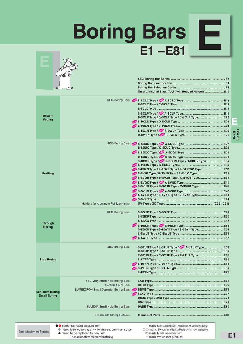 Каталог Sumitomo токарные резцы (державки) для внутреннего точения
 Общий каталог Sumitomo 2018 - 2019
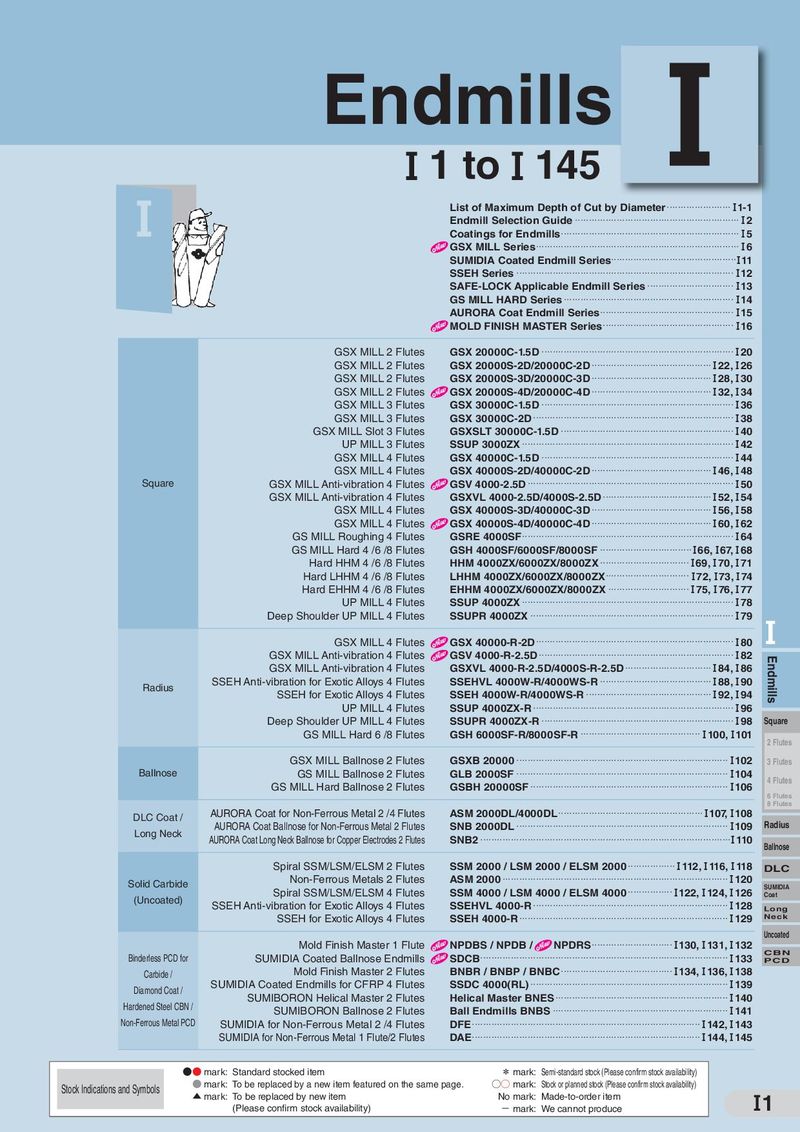 Каталог Sumitomo монолитные фрезы
- H001
- H002
- H003
- H004
- H005
- H006
- H007
- H008
- H009
- H010
- H011
- H012
- H013
- H014
- H015
- H016
- H017
- H018
- H019
- H020
- H021
- H022
- H023
- H024
- H025
- H026
- H027
- H028
- H029
- H030
- H031
- H032
- H033
- H034
- H035
- H036
- H037
- H038
- H039
- H040
- H041
- H042
- H043
- H044
- H045
- H046
- H047
- H048
- H049
- H050
- H051
- H052
- H053
- H054
- H055
- H056
- H057
- H058
- H059
- H060
- H061
- H062
- H063
- H064
- H065
- H066
- H067
- H068
- H069
- H070
- H071
- H072
- H073
- H074
- H075
- H076
- H077
- H078
- H079
- H080
- H081
- H082
- H083
- H084
- H085
- H086
- H087
- H088
- H089
- H090
- H091
- H092
- H093
- H094
- H095
- H096
- H097
- H098
- H099
- H100
- H101
- H102
- H103
- H104
- H105
- H106
- H107
- H108
- H109
- H110
- H111
- H112
- H113
- H114
- H115
- H116
- H117
- H118
- H119
- H120
- H121
- H122
- H123
- H124
- H125
- H126
- H127
- H128
- H129
- H130
- H131
- H132
- H133
- H134
- H135
- H136
- H137
- H138
- H139
- H140
- H141
- H142
- H143
- H144
- H145
- H146
- H147
- H148
- H149
- H150
- H151
- H152
- H153
- H154
- H155
- H156
- H157
- H158
- H159
- H160
- H161
- H162
- H163
- H164
- H165
- H166
- H167
- H168
- H169
- H170
- H171
- H172
- H173
- H174

SEC-Sumi Power Mill
PWS(F) / PWSR Type
- General Features
Highly reliable shoulder milling cutter with tangentially mounted for never-
before-possible high cutting edge strength and sharp cutting edges.
A 2-step insert array structure creates a new
PWSR Type to meet the needs of deep cutting.
- Characteristics
Tangentially mounted inserts for outstanding cutting edge strength combined with optimised breaker for outstanding edge sharpness and cutting ability.
- Nicked insert design created with high-precision molding technology allows stable milling even in applications with large tool overhang.
- New ACP and ACK milling grades are used to meet the needs of various types of work material.
- Performance
- Performance Comparison with General-purpose G-type Inserts
- Cutting Edge Strength Comparison
- Comparison of Cutting Force
High cutting edge strength for excellent stability! Cutting that is nearly the same as screw-on type!!
1,000 3,000 1st Step Principal Force 2nd Step Feed Force
3rd Step 2,500 Back Force
800 ○:No breakage, edge OK × : 2,000
Breakage, 600 unusable 1,500 Cutting Conditions Cutting Conditions
| 400 | vc=150m/min | vc=150m/min | |
| fz=0.20mm/t | 1,000 | fz=0.20mm/t | |
| ae =3mm | a e=3mm | ||
| ap =10mm | a p=10mm | ||
| 200 | 500 | ||
| Dry | Dry | ||
| Work Material: S50C | H Work Material: S50C | ||
| Tool Diameter: 80mm | Tool Diameter :80mm | ||
| 0 | 0 |
| Sumi Power Mill | Competitor A | Competitor B | Sumi Power Mill | Competitor A | Competitor B |
| PWS Type | (Screw-on) | (Tangential) | PWS Type | (Screw-on) | (Tangential) |
- Performance Comparison with Nicked R Type Inserts
Nicked R Type Inserts General-Purpose G Type Inserts Comparison of Cutting Force
Reduced cutting power and excellent vibration resistance! Face 7,000 Milling
R Type
| Reduced 25%!! | G Type | Shoulder | ||
| 6,000 | Milling | |||
| 5,000 | High Feed | |||
| s! |
chip 4,000 Radius
Small Multi- 3,000 Cutting Conditions Purpose
v c=200m/min R/
| 2,000 | fz=0.15mm/t | Profiling |
| ae=20mm | ||
| ap=10mm | Groove/ | |
| 1,000 | Dry | T-Slot |
Work Material:S50C Tool Diameter:100mm 0 Chamfering Nicked R Type General Machining (G-Type)
) Aluminum/
| Cautions when Using Nicked R Type Inserts | 1 | Note for inserts set-up | Light Alloys | |
| 4 Nicks4 Nicks | ||||
| (Corners 1 and 4)(Corners 1 and 4) | When using R type nicked indexable inserts, attach them so that | High-Speed | ||
| Cast Iron | ||||
| the nicked grooves alternate as shown in the image to the left. | ||||
| ③ | ④ | 2)Note for cutting condition |
In order to attach as shown in the image to the left, the feed rate per tooth is double that when attaching the same-shaped inserts on all teeth. This means ④ that adjustments should be made so the upper feed limit is as shown below. f =0.25mm/t
3 Nicks 3 Nicks z
(Corners 2 and 3)(Corners 2 and 3) Example: Use at f =0.2mm/t
z
Feed when all teeth are normal: 0.2mm/t
③ ③ Feed when nicked: 0.4mm/t
④ Any incorrect use of inserts may damage tools.