Каталог Sumitomo фрезы со сменными пластинами - страница 117
Навигация
 Каталог Sumitomo инструмент для обработки канавок
 Общий каталог Sumitomo 2019 - 2020
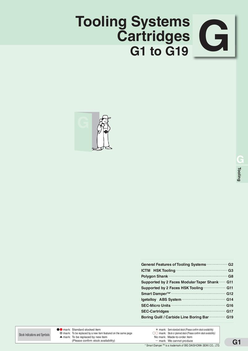 Каталог Sumitomo модульные системы для револьверных головок токарных станков
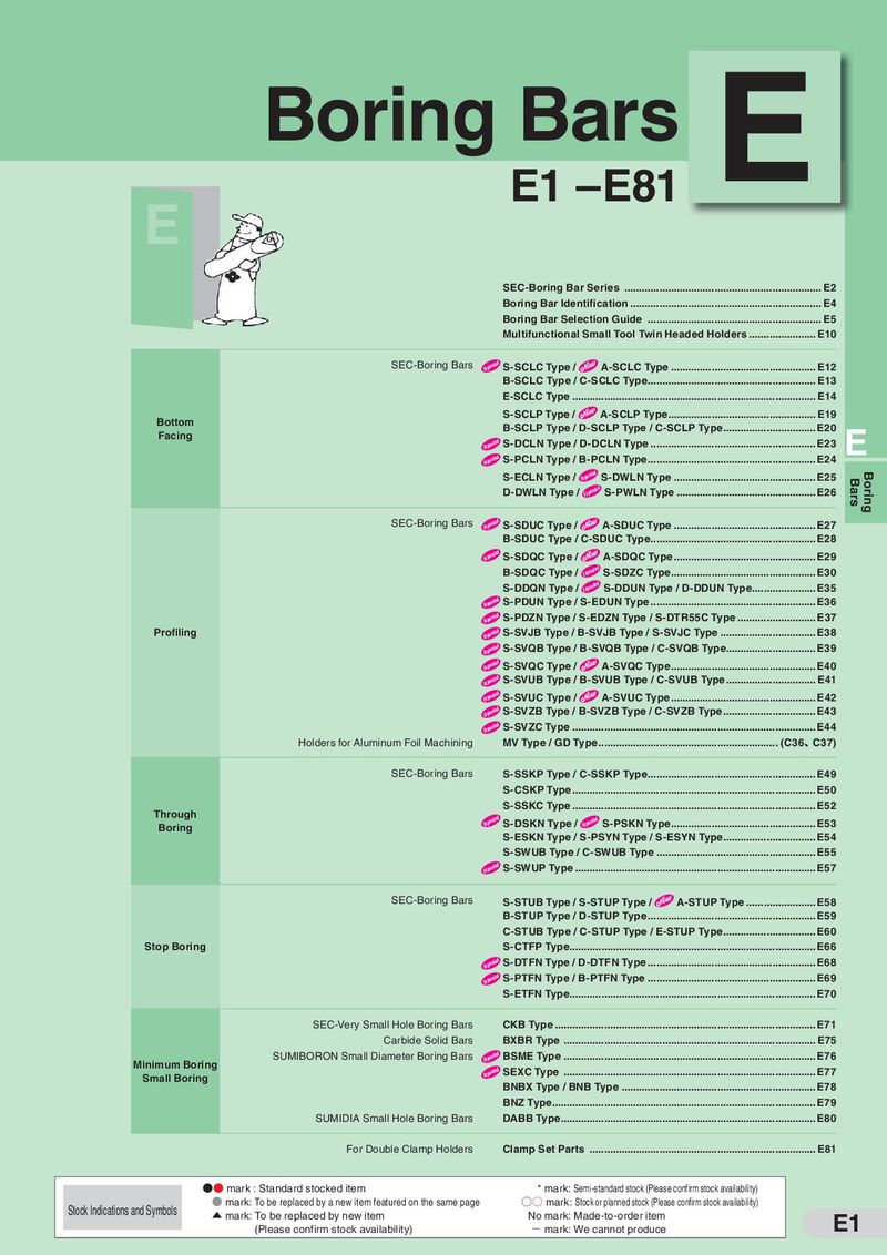 Каталог Sumitomo токарные резцы (державки) для внутреннего точения
 Общий каталог Sumitomo 2018 - 2019
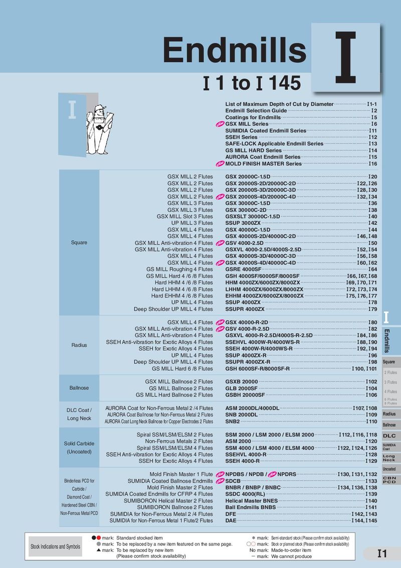 Каталог Sumitomo монолитные фрезы
- H001
- H002
- H003
- H004
- H005
- H006
- H007
- H008
- H009
- H010
- H011
- H012
- H013
- H014
- H015
- H016
- H017
- H018
- H019
- H020
- H021
- H022
- H023
- H024
- H025
- H026
- H027
- H028
- H029
- H030
- H031
- H032
- H033
- H034
- H035
- H036
- H037
- H038
- H039
- H040
- H041
- H042
- H043
- H044
- H045
- H046
- H047
- H048
- H049
- H050
- H051
- H052
- H053
- H054
- H055
- H056
- H057
- H058
- H059
- H060
- H061
- H062
- H063
- H064
- H065
- H066
- H067
- H068
- H069
- H070
- H071
- H072
- H073
- H074
- H075
- H076
- H077
- H078
- H079
- H080
- H081
- H082
- H083
- H084
- H085
- H086
- H087
- H088
- H089
- H090
- H091
- H092
- H093
- H094
- H095
- H096
- H097
- H098
- H099
- H100
- H101
- H102
- H103
- H104
- H105
- H106
- H107
- H108
- H109
- H110
- H111
- H112
- H113
- H114
- H115
- H116
- H117
- H118
- H119
- H120
- H121
- H122
- H123
- H124
- H125
- H126
- H127
- H128
- H129
- H130
- H131
- H132
- H133
- H134
- H135
- H136
- H137
- H138
- H139
- H140
- H141
- H142
- H143
- H144
- H145
- H146
- H147
- H148
- H149
- H150
- H151
- H152
- H153
- H154
- H155
- H156
- H157
- H158
- H159
- H160
- H161
- H162
- H163
- H164
- H165
- H166
- H167
- H168
- H169
- H170
- H171
- H172
- H173
- H174
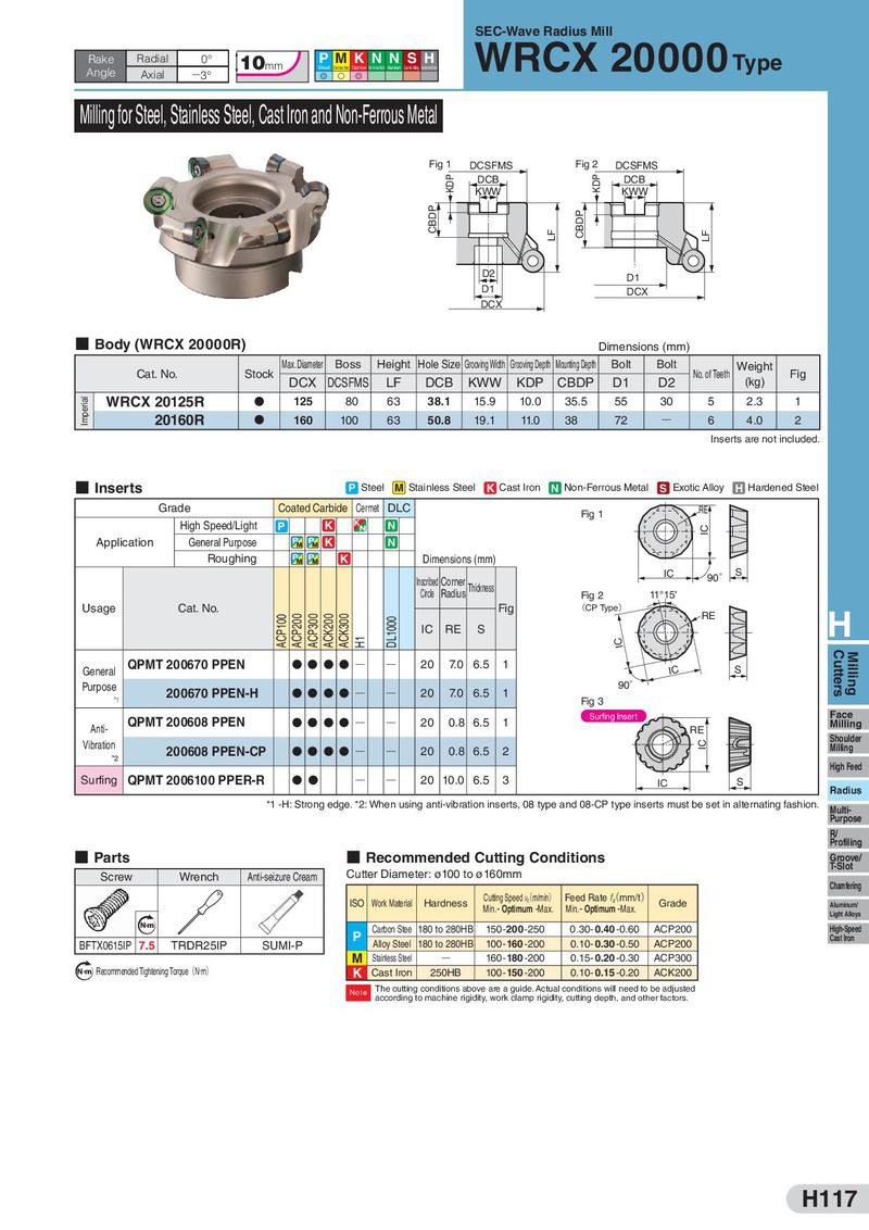
WRCX 20000SEC-Wave Radius Mill
| Rake | Radial | 0° | 10 | P M K N N S H | Type | ||
| Axial | 3° | G | S | G |
Milling for Steel, Stainless Steel, Cast Iron and Non-Ferrous Metal
Fig 1 DCSFMS Fig 2 DCSFMS
DCB DCB KWW KWW
D2 D1 D1 DCX DCX
- Body (WRCX 20000R)
Dimensions (mm)
Max. Diameter Boss Height Hole Size Grooving Width Grooving Depth Mounting Depth Bolt Bolt Weight
Cat. No. Stock No. of Teeth Fig
| DCX DCSFMS | LF | DCB | KWW | KDP | CBDP | D1 | D2 | (kg) | ||||||
| WRCX 20125R | D | 125 | 80 | 63 | 38.1 | 15.9 10.0 35.5 | 55 | 30 | 5 | 2.3 | 1 | |||
| 20160R | D | 160 | 100 | 63 | 50.8 | 19.1 11.0 38 | 72 | Q | 6 | 4.0 2 |
Inserts are not included.
- Inserts
P Steel M Stainless Steel K Cast Iron N Non-Ferrous Metal S Exotic Alloy H Hardened Steel
| Grade | Coated Carbide Cermet DLC | RE | |
| Fig 1 |
| High Speed/Light | P | K | N | |
| Application | General Purpose | K | N |
Roughing K Dimensions (mm)
| IC | ° | S | ||
| Inscribed Corner | 90 | |||
| Thickness |
Circle Radius Fig 2 11°15'
| Usage | Cat. No. | Fig | (CP Type) | ||
| RE | H |
| IC | RE | S | |
| IC |
QPMT 200670 PPEN DDDDQ Q 20 7.0 6.5 1
| General | IC | S | |
| Purpose | 90° |
| 200670 PPEN-H DDDDQ | Q | 20 7.0 6.5 | 1 | ||
| *1 | Fig 3 | ||||
| DDDDQ | Q | Surfing Insert Face | |||
| QPMT 200608 PPEN | 20 0.8 6.5 | 1 | Milling | ||
| Anti- | RE | ||||
| Shoulder | |||||
| Vibration | DDDDQ | Q | Milling | ||
| 200608 PPEN-CP | 20 0.8 6.5 | 2 | |||
| * 2 | |||||
| High Feed | |||||
| Surfing | QPMT 2006100 PPER-R D D | Q Q | 20 10.0 6.5 | 3 |
IC S Radius *1 -H: Strong edge. *2: When using anti-vibration inserts, 08 type and 08-CP type inserts must be set in alternating fashion. Multi-
Purpose R/ Profiling
- Parts
- Recommended Cutting Conditions
Groove/ T-Slot
| Screw | Wrench | Anti-seizure Cream | Cutter Diameter: ø100 to ø160mm | |||
| Chamfering | ||||||
| Cutting Speed v(m/min) | Feed Rate f(mm/t) |
ISO Work Material Hardness c z Grade
| Min.- Optimum -Max. | Min.- Optimum -Max. | Aluminum/ | ||||||
| Light Alloys | ||||||||
| N m | Carbon Stee 180 to 280HB | 150-200-250 | 0.30-0.40 -0.60 | ACP200 | High-Speed | |||
| P | Cast Iron | |||||||
| BFTX0615IP | 7.5 | SUMI-P TRDR25IP | Alloy Steel 180 to 280HB | 100-160 -200 | 0.10- 0.30 -0.50 | ACP200 | ||
| M | Stainless Steel | Q | 160-180 -200 | 0.15-0.20 -0.30 | ACP300 | |||
| Recommended Tightening Torque(N・m) | ||||||||
| N m | K | Cast Iron | 250HB | 100-150 -200 | 0.10- 0.15 -0.20 | ACK200 |
The cutting conditions above are a guide. Actual conditions will need to be adjusted Note according to machine rigidity, work clamp rigidity, cutting depth, and other factors.