Каталог Sumitomo фрезы со сменными пластинами - страница 121
Навигация
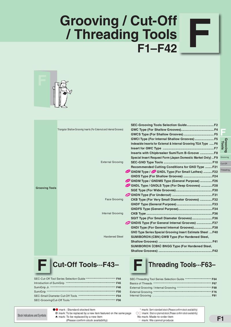 Каталог Sumitomo инструмент для обработки канавок
 Общий каталог Sumitomo 2019 - 2020
 Каталог Sumitomo модульные системы для револьверных головок токарных станков
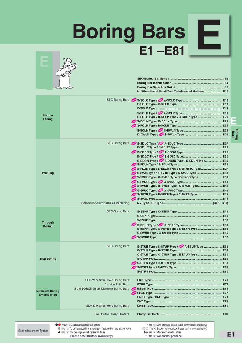 Каталог Sumitomo токарные резцы (державки) для внутреннего точения
 Общий каталог Sumitomo 2018 - 2019
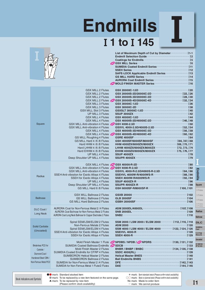 Каталог Sumitomo монолитные фрезы
- H001
- H002
- H003
- H004
- H005
- H006
- H007
- H008
- H009
- H010
- H011
- H012
- H013
- H014
- H015
- H016
- H017
- H018
- H019
- H020
- H021
- H022
- H023
- H024
- H025
- H026
- H027
- H028
- H029
- H030
- H031
- H032
- H033
- H034
- H035
- H036
- H037
- H038
- H039
- H040
- H041
- H042
- H043
- H044
- H045
- H046
- H047
- H048
- H049
- H050
- H051
- H052
- H053
- H054
- H055
- H056
- H057
- H058
- H059
- H060
- H061
- H062
- H063
- H064
- H065
- H066
- H067
- H068
- H069
- H070
- H071
- H072
- H073
- H074
- H075
- H076
- H077
- H078
- H079
- H080
- H081
- H082
- H083
- H084
- H085
- H086
- H087
- H088
- H089
- H090
- H091
- H092
- H093
- H094
- H095
- H096
- H097
- H098
- H099
- H100
- H101
- H102
- H103
- H104
- H105
- H106
- H107
- H108
- H109
- H110
- H111
- H112
- H113
- H114
- H115
- H116
- H117
- H118
- H119
- H120
- H121
- H122
- H123
- H124
- H125
- H126
- H127
- H128
- H129
- H130
- H131
- H132
- H133
- H134
- H135
- H136
- H137
- H138
- H139
- H140
- H141
- H142
- H143
- H144
- H145
- H146
- H147
- H148
- H149
- H150
- H151
- H152
- H153
- H154
- H155
- H156
- H157
- H158
- H159
- H160
- H161
- H162
- H163
- H164
- H165
- H166
- H167
- H168
- H169
- H170
- H171
- H172
- H173
- H174
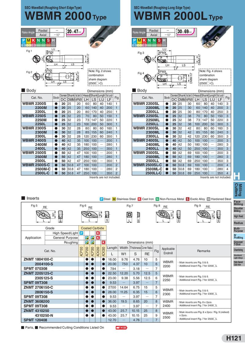
SEC-WaveBall (Roughing Short Edge Type) SEC-WaveBall (Roughing Long Edge Type) WBMR 2000 Type WBMR 2000L Type Rake Angle Radial ー 20 to 47mm Rake Angle Radial ー 30 to 69mm Axial −10° Axial −10° P MKN N SH P M K N N SH Steel Stainless Steel Cast Iron Non-Ferrous Metal Aluminum Exotic Alloy Hardened Steel Steel Stainless Steel Cast Iron Non-Ferrous Metal Aluminum Exotic Alloy Hardened Steel G S G G S G Fig 1 LU LU APMX DMM h7 Fig 3 APMX DC DC DMM h7 LH LS LH LS LF LF Fig 2 APMX DMM h7 Note: Fig. 2 shows APMX Note: Fig. 4 shows DC combination Fig 4 DMM h7 combination shank diagram DC shank diagram LH LS (2500□-C). LH LS (2500□-C). LF LF ■ Body Dimensions (mm) ■ Body Dimensions (mm) Cat. No. Stock Diameter Shank Max. Depth of Cut Head Shank Length Total Length Fig Cat. No. Stock Diameter Shank Max. Depth of Cut Head Shank Length Total Length Fig DC DMM APMX LH LS LU LF DC DMM APMX LH LS LU LF WBMR 2200S D 20 25 20 60 80 40 140 1 WBMR 2200SL D 20 25 30 60 80 40 140 3 2200M D 20 25 20 60 140 40 200 1 2200ML D 20 25 30 60 140 40 200 3 2200L D 20 25 20 80 170 40 250 1 2200LL D 20 25 30 80 170 40 250 3 WBMR 2250S D 25 32 23 70 80 50 150 1 WBMR 2250SL D 25 32 38 70 80 50 150 3 2250M D 25 32 23 73 147 50 220 1 2250ML D 25 32 38 73 147 50 220 3 2250L D 25 32 23 100 200 50 300 1 2250LL D 25 32 38 100 200 50 300 3 WBMR 2300S D 30 32 28 80 80 60 160 1 WBMR 2300SL D 30 32 42 80 80 60 160 3 2300M D 30 32 28 85 155 60 240 1 2300ML D 30 32 42 85 155 60 240 3 2300L D 30 32 28 120 230 60 350 1 2300LL D 30 32 42 120 230 60 350 3 WBMR 2400S D 40 42 35 100 100 Q 200 1 WBMR 2400SL D 40 42 50 100 100 Q 200 3 2400M D 40 42 35 180 100 Q 280 1 2400ML D 40 42 50 180 100 Q 280 3 2400L D 40 42 35 250 100 Q 350 1 2400LL D 40 42 50 250 100 Q 350 3 WBMR 2500S D 50 42 47 100 100 Q 200 1 WBMR 2500SL D 50 42 69 100 100 Q 200 3 2500M D 50 42 47 180 100 Q 280 1 2500ML D 50 42 69 180 100 Q 280 3 2500L D 50 42 47 250 100 Q 350 1 2500LL D 50 42 69 250 100 Q 350 3 WBMR 2500S-C D 50 50.8 47 100 100 Q 200 2 WBMR 2500SL-C D 50 50.8 69 100 100 Q 200 4 2500M-C D 50 50.8 47 180 100 Q 280 2 2500ML-C D 50 50.8 69 180 100 Q 280 4 2500L-C D 50 50.8 47 250 100 Q 350 2 2500LL-C D 50 50.8 69 250 100 Q 350 4 H Inserts are not included. Inserts are not included. Cutters Milling ■ Inserts P Steel M Stainless Steel K Cast Iron N Non-Ferrous Metal S Exotic Alloy H Hardened Steel Face Milling Fig 5 Fig 6 Fig 7 Fig 8 RE Fig 9 RE RE RE Shoulder Milling W1 W1 W1 W1 High Feed L S L S L S L S L S Radius Grade Coated Carbide Multi- High Speed/Light P K Purpose Application General Purpose K R/ Profiling Roughing K Dimensions (mm) Groove/ T-Slot ACP100 ACP200 ACP300 ACK200 ACK300 Length Width Thickness Corner Radius Applicable Chamfering Cat. No. L W1 S RE Fig Endmill Remarks Aluminum/ ZNMT 1804100-C D D D 18.00 9.76 4.76 10 5 Light Alloys 2004100-S D D D 20.00 7.50 4.37 10 6 WBMR ・Main inserts are Fig. 5 & 6. High-Speed 2200 ・Additional insert Fig. 7 for 2200□L Cast Iron SPMT 070308 D D D 7.94 Q 3.18 Q 7 ZNMT 2205125-C D D D 22.50 12.20 5.70 12.5 5 WBMR 2305125-S D D D 23.00 9.38 5.56 12.5 6 ・Main inserts are Fig. 5 & 6. 2250 ・Additional insert Fig. 7 for 2250□L SPMT 09T308 D D D 9.53 Q 3.97 Q 7 ZNMT 2706150-C D D D 27.00 14.64 6.75 15 5 WBMR 2806150-S D D D 28.00 11.25 6.35 15 6 ・Main inserts are Fig. 5 & 6. 2300 ・Additional insert Fig. 7 for 2300□L SPMT 09T308 D D D 9.53 Q 3.97 Q 7 ZNMT 3608200 D D D 36.00 19.5 8.65 20 8 WBMR ・Main inserts are Fig. 8 x 2pcs. SPMT 09T308 D D D 9.53 Q 3.97 Q 7 2400 ・Additional insert Fig. 7 for 2400□L ZNMT 4310250 D D D 43.00 25.7 10.15 25 8 WBMR ・Main inserts use Fig. 8 x 2pcs / Fig. 9 (nicked) 4310250-N D D D 43.00 25.7 10.15 25 9 2500 x 2pcs. SPMT 120408 12.70 Q 4.76 Q 7 ・Additional insert Fig. 7 for 2500□L ■ Parts, ■ Recommended Cutting Conditions Listed On H120 H121