Модульные инструментальные системы линейки KM4X Kennametal 2017 - страница 122
Навигация
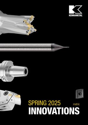 Новинки Kennametal - весна 2025
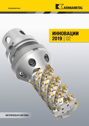 Каталог Kennametal инновации 2019.2
 Инновационные токарные пластины с покрытиями KENGold CVD и PVD Kennametal 2025
 Сменные фрезерные пластины сплавов KCK20B и KCKP10 Kennametal 2024
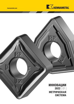 Каталог Kennametal инновации 2022.1
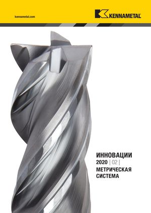 Каталог Kennametal инновации 2020.2
- __KMT_KM4X_COVER_EN_Covers_EN_in
- KMT_KM4X_Catalog_A000_A001_EN
- KMT_KM4X_Catalog_A002_A003_EN
- KMT_KM4X_Catalog_A004_A005_EN
- KMT_KM4X_Catalog_A006_A007_EN
- KMT_KM4X_Catalog_A008_A009_EN
- KMT_KM4X_Catalog_A010_A011_EN
- KMT_KM4X_Catalog_B000_B001_EN
- KMT_KM4X_Catalog_B002_B003_EN
- KMT_KM4X_Catalog_B004_B005_EN
- KMT_KM4X_Catalog_B006_B007_EN
- KMT_KM4X_Catalog_B008_B009_EN
- KMT_KM4X_Catalog_B010_B011_EN
- KMT_KM4X_Catalog_B012_B013_EN
- KMT_KM4X_Catalog_B014_B015_EN
- KMT_KM4X_Catalog_B016_B017_EN
- KMT_KM4X_Catalog_B018_B019_EN
- KMT_KM4X_Catalog_B020_B021_EN
- KMT_KM4X_Catalog_B022_B023_EN
- KMT_KM4X_Catalog_B024_B025_EN
- KMT_KM4X_Catalog_B026_B027_EN
- KMT_KM4X_Catalog_B028_B029_EN
- KMT_KM4X_Catalog_B030_B031_EN
- KMT_KM4X_Catalog_B032_B033_EN
- KMT_KM4X_Catalog_B034_B035_EN
- KMT_KM4X_Catalog_B036_B037_EN
- KMT_KM4X_Catalog_B038_B039_EN
- KMT_KM4X_Catalog_B040_B041_EN
- KMT_KM4X_Catalog_B042_B043_EN
- KMT_KM4X_Catalog_B044_B045_EN
- KMT_KM4X_Catalog_B046_B047_EN
- KMT_KM4X_Catalog_B048_B049_EN
- KMT_KM4X_Catalog_B050_B051_EN
- KMT_KM4X_Catalog_B052_B053_EN
- KMT_KM4X_Catalog_B054_B055_EN
- KMT_KM4X_Catalog_B056_B057_EN
- KMT_KM4X_Catalog_B058_B059_EN
- KMT_KM4X_Catalog_B060_B061_EN
- KMT_KM4X_Catalog_B062_B063_EN
- KMT_KM4X_Catalog_B064_B065_EN
- KMT_KM4X_Catalog_B066_B067_EN
- KMT_KM4X_Catalog_B068_B069_EN
- KMT_KM4X_Catalog_B070_B071_EN
- KMT_KM4X_Catalog_B072_B073_EN
- KMT_KM4X_Catalog_B074_B075_EN
- KMT_KM4X_Catalog_B076_B077_EN
- KMT_KM4X_Catalog_B078_B079_EN
- KMT_KM4X_Catalog_B080_B081_EN
- KMT_KM4X_Catalog_B082_B083_EN
- KMT_KM4X_Catalog_B084_B085_EN
- KMT_KM4X_Catalog_C000_C001_EN
- KMT_KM4X_Catalog_C002_C003_EN
- KMT_KM4X_Catalog_C004_C005_EN
- KMT_KM4X_Catalog_C006_C007_EN
- KMT_KM4X_Catalog_C008_C009_EN
- KMT_KM4X_Catalog_C010_C011_EN
- KMT_KM4X_Catalog_C012_C013_EN
- KMT_KM4X_Catalog_C014_C015_EN
- KMT_KM4X_Catalog_C016_C017_EN
- KMT_KM4X_Catalog_C018_C019_EN
- KMT_KM4X_Catalog_C020_C021_EN
- KMT_KM4X_Catalog_C022_C023_EN
- KMT_KM4X_Catalog_C024_C025_EN
- KMT_KM4X_Catalog_C026_C027_EN
- KMT_KM4X_Catalog_C028_C029_EN
- KMT_KM4X_Catalog_C030_C031_EN
- KMT_KM4X_Catalog_C032_C033_EN
- KMT_KM4X_Catalog_C034_C035_EN
- KMT_KM4X_Catalog_C036_C037_EN
- KMT_KM4X_Catalog_C038_C039_EN
- KMT_KM4X_Catalog_C040_EN
- __KMT_KM4X_COVER_EN_Covers_EN_in
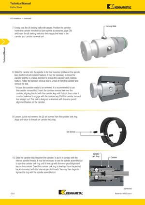
6.2 Установка — продолжение
7. Равномерно покройте четыре фиксирующих шарика смазкой. Поместите канистр в инструмент для снятия канистра (см. аксессуары шпинделя, страница C8) и вставьте четыре фиксирующих шарика в соответствующие отверстия в канистре и инструменте для снятия канистра.
8. Сдвиньте канистр в шпиндель в его окончательное установленное положение в канале шпинделя (нижняя часть антиротационного элемента). Может быть необходимо слегка переместить канистр в радиальном направлении, чтобы выровнять антиротационный элемент канистра. Поворачивайте инструмент для снятия канистра, чтобы отсоединить его от канистра, и извлеките инструмент.
Примечание: Если канистр требуется снять, рекомендуется использовать инструмент для снятия канистра. Вставьте инструмент для снятия канистра над канистром, выровняв паз с ключом канистра до упора, затем поворачивайте его против часовой стрелки, чтобы зацепиться с ключом канистра. Извлеките инструмент для снятия канистра прямо вверх. Этот инструмент предназначен для взаимодействия с защитой от ошибок / элементом выравнивания канистра.
9. Ослабьте, но не снимайте два установочных винта стопорного кольца канистра. Нанесите состав против заедания на резьбу стопорного кольца канистра.
10. Сдвиньте стопорное кольцо канистра над канистром. Чтобы привести его в контакт с внутренней резьбой шпинделя, может потребоваться использовать инструмент для сборки шпинделя, чтобы провернуть стопорное кольцо канистра до выравнивания с защитой от ошибок / ключом выравнивания канистра. После выравнивания стопорного кольца канистра его можно прижать к контакту с внутренней резьбой шпинделя. Затем можно начинать затягивание кольца с помощью инструмента для сборки шпинделя.