Модульные инструментальные системы линейки KM4X Kennametal 2017 - страница 123
Навигация
 Новинки Kennametal - весна 2025
 Каталог Kennametal инновации 2019.2
 Инновационные токарные пластины с покрытиями KENGold CVD и PVD Kennametal 2025
 Сменные фрезерные пластины сплавов KCK20B и KCKP10 Kennametal 2024
 Каталог Kennametal инновации 2022.1
 Каталог Kennametal инновации 2020.2
- __KMT_KM4X_COVER_EN_Covers_EN_in
- KMT_KM4X_Catalog_A000_A001_EN
- KMT_KM4X_Catalog_A002_A003_EN
- KMT_KM4X_Catalog_A004_A005_EN
- KMT_KM4X_Catalog_A006_A007_EN
- KMT_KM4X_Catalog_A008_A009_EN
- KMT_KM4X_Catalog_A010_A011_EN
- KMT_KM4X_Catalog_B000_B001_EN
- KMT_KM4X_Catalog_B002_B003_EN
- KMT_KM4X_Catalog_B004_B005_EN
- KMT_KM4X_Catalog_B006_B007_EN
- KMT_KM4X_Catalog_B008_B009_EN
- KMT_KM4X_Catalog_B010_B011_EN
- KMT_KM4X_Catalog_B012_B013_EN
- KMT_KM4X_Catalog_B014_B015_EN
- KMT_KM4X_Catalog_B016_B017_EN
- KMT_KM4X_Catalog_B018_B019_EN
- KMT_KM4X_Catalog_B020_B021_EN
- KMT_KM4X_Catalog_B022_B023_EN
- KMT_KM4X_Catalog_B024_B025_EN
- KMT_KM4X_Catalog_B026_B027_EN
- KMT_KM4X_Catalog_B028_B029_EN
- KMT_KM4X_Catalog_B030_B031_EN
- KMT_KM4X_Catalog_B032_B033_EN
- KMT_KM4X_Catalog_B034_B035_EN
- KMT_KM4X_Catalog_B036_B037_EN
- KMT_KM4X_Catalog_B038_B039_EN
- KMT_KM4X_Catalog_B040_B041_EN
- KMT_KM4X_Catalog_B042_B043_EN
- KMT_KM4X_Catalog_B044_B045_EN
- KMT_KM4X_Catalog_B046_B047_EN
- KMT_KM4X_Catalog_B048_B049_EN
- KMT_KM4X_Catalog_B050_B051_EN
- KMT_KM4X_Catalog_B052_B053_EN
- KMT_KM4X_Catalog_B054_B055_EN
- KMT_KM4X_Catalog_B056_B057_EN
- KMT_KM4X_Catalog_B058_B059_EN
- KMT_KM4X_Catalog_B060_B061_EN
- KMT_KM4X_Catalog_B062_B063_EN
- KMT_KM4X_Catalog_B064_B065_EN
- KMT_KM4X_Catalog_B066_B067_EN
- KMT_KM4X_Catalog_B068_B069_EN
- KMT_KM4X_Catalog_B070_B071_EN
- KMT_KM4X_Catalog_B072_B073_EN
- KMT_KM4X_Catalog_B074_B075_EN
- KMT_KM4X_Catalog_B076_B077_EN
- KMT_KM4X_Catalog_B078_B079_EN
- KMT_KM4X_Catalog_B080_B081_EN
- KMT_KM4X_Catalog_B082_B083_EN
- KMT_KM4X_Catalog_B084_B085_EN
- KMT_KM4X_Catalog_C000_C001_EN
- KMT_KM4X_Catalog_C002_C003_EN
- KMT_KM4X_Catalog_C004_C005_EN
- KMT_KM4X_Catalog_C006_C007_EN
- KMT_KM4X_Catalog_C008_C009_EN
- KMT_KM4X_Catalog_C010_C011_EN
- KMT_KM4X_Catalog_C012_C013_EN
- KMT_KM4X_Catalog_C014_C015_EN
- KMT_KM4X_Catalog_C016_C017_EN
- KMT_KM4X_Catalog_C018_C019_EN
- KMT_KM4X_Catalog_C020_C021_EN
- KMT_KM4X_Catalog_C022_C023_EN
- KMT_KM4X_Catalog_C024_C025_EN
- KMT_KM4X_Catalog_C026_C027_EN
- KMT_KM4X_Catalog_C028_C029_EN
- KMT_KM4X_Catalog_C030_C031_EN
- KMT_KM4X_Catalog_C032_C033_EN
- KMT_KM4X_Catalog_C034_C035_EN
- KMT_KM4X_Catalog_C036_C037_EN
- KMT_KM4X_Catalog_C038_C039_EN
- KMT_KM4X_Catalog_C040_EN
- __KMT_KM4X_COVER_EN_Covers_EN_in
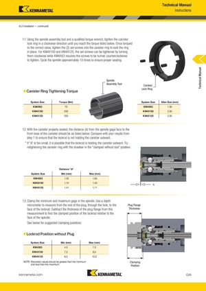
6.2 Установка — продолжение
11. Используя инструмент для сборки шпинделя и квалифицированный динамометрический ключ, затягивайте стопорное кольцо канистра в направлении по часовой стрелке до достижения крутящего момента, указанного ниже. После затяжки до правильного значения затяните два установочных винта в стопорное кольцо, чтобы зафиксировать кольцо на месте. Для KM4X100 и KM4X125 установочные винты можно затягивать, поворачивая их по часовой стрелке, в то время как KM4X63 требует поворачивания винтов против часовой стрелки для затяжки. Проведите цикл шпинделя примерно 10 раз, чтобы обеспечить правильное седло.
| Размер системы | Крутящий момент (Нм) |
|---|---|
| KM4X63 | 75 |
| KM4X100 | 200 |
| KM4X125 | 350 |
| Размер системы | Размер шестигранника (мм) |
|---|---|
| KM4X63 | 1,50 |
| KM4X100 | 2,00 |
| KM4X125 | 2,00 |
12. При правильном положении канистра расстояние (A) от торца калибра шпинделя до переднего носика канистра должно быть таким, как указано ниже. Сравните с вашими результатами из этапа 1, чтобы убедиться, что резьбовой стержень не удерживает канистр снаружи.
Примечание: Если «A» слишком мала, возможно, резьбовой стержень удерживает канистр снаружи. Попробуйте повторно затянуть стопорное кольцо канистра с обоймой в положении «зажата без инструмента».
| Размер системы | Мин (мм) | Макс (мм) |
|---|---|---|
| KM4X63 | 1,35 | 1,65 |
| KM4X100 | 1,10 | 1,40 |
| KM4X125 | 1,41 | 1,71 |
13. Зажмите минимальный и максимальный калибр в шпинделе. Используйте микрометр глубины, чтобы измерить от конца пробки через отверстие до грани резьбового стержня. Вычтите толщину фланца пробки из этого измерения, чтобы найти зажатое положение резьбового стержня относительно торца шпинделя. См. ниже рекомендуемые позиции зажима:
| Размер системы | Мин (мм) | Макс (мм) |
|---|---|---|
| KM4X63 | 4,5 | 7,0 |
| KM4X100 | 7,0 | 8,5 |
| KM4X125 | 8,0 | 10,0 |
Примечание: Записанные значения должны быть больше минимума и меньше максимума.