Модульные инструментальные системы линейки KM4X Kennametal 2017 - страница 112
Навигация
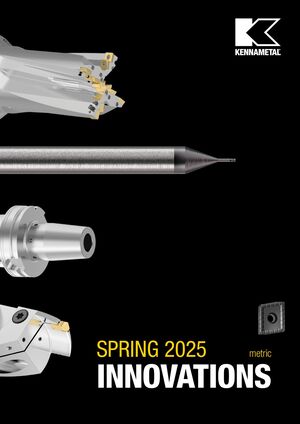 Новинки Kennametal - весна 2025
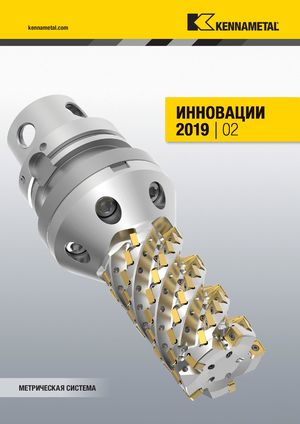 Каталог Kennametal инновации 2019.2
 Инновационные токарные пластины с покрытиями KENGold CVD и PVD Kennametal 2025
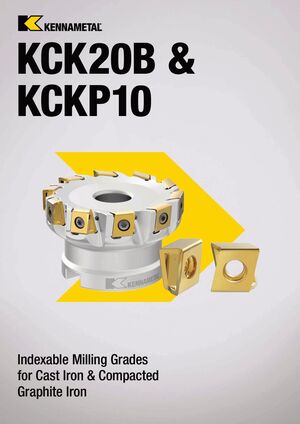 Сменные фрезерные пластины сплавов KCK20B и KCKP10 Kennametal 2024
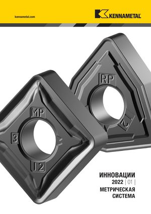 Каталог Kennametal инновации 2022.1
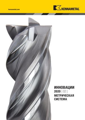 Каталог Kennametal инновации 2020.2
- __KMT_KM4X_COVER_EN_Covers_EN_in
- KMT_KM4X_Catalog_A000_A001_EN
- KMT_KM4X_Catalog_A002_A003_EN
- KMT_KM4X_Catalog_A004_A005_EN
- KMT_KM4X_Catalog_A006_A007_EN
- KMT_KM4X_Catalog_A008_A009_EN
- KMT_KM4X_Catalog_A010_A011_EN
- KMT_KM4X_Catalog_B000_B001_EN
- KMT_KM4X_Catalog_B002_B003_EN
- KMT_KM4X_Catalog_B004_B005_EN
- KMT_KM4X_Catalog_B006_B007_EN
- KMT_KM4X_Catalog_B008_B009_EN
- KMT_KM4X_Catalog_B010_B011_EN
- KMT_KM4X_Catalog_B012_B013_EN
- KMT_KM4X_Catalog_B014_B015_EN
- KMT_KM4X_Catalog_B016_B017_EN
- KMT_KM4X_Catalog_B018_B019_EN
- KMT_KM4X_Catalog_B020_B021_EN
- KMT_KM4X_Catalog_B022_B023_EN
- KMT_KM4X_Catalog_B024_B025_EN
- KMT_KM4X_Catalog_B026_B027_EN
- KMT_KM4X_Catalog_B028_B029_EN
- KMT_KM4X_Catalog_B030_B031_EN
- KMT_KM4X_Catalog_B032_B033_EN
- KMT_KM4X_Catalog_B034_B035_EN
- KMT_KM4X_Catalog_B036_B037_EN
- KMT_KM4X_Catalog_B038_B039_EN
- KMT_KM4X_Catalog_B040_B041_EN
- KMT_KM4X_Catalog_B042_B043_EN
- KMT_KM4X_Catalog_B044_B045_EN
- KMT_KM4X_Catalog_B046_B047_EN
- KMT_KM4X_Catalog_B048_B049_EN
- KMT_KM4X_Catalog_B050_B051_EN
- KMT_KM4X_Catalog_B052_B053_EN
- KMT_KM4X_Catalog_B054_B055_EN
- KMT_KM4X_Catalog_B056_B057_EN
- KMT_KM4X_Catalog_B058_B059_EN
- KMT_KM4X_Catalog_B060_B061_EN
- KMT_KM4X_Catalog_B062_B063_EN
- KMT_KM4X_Catalog_B064_B065_EN
- KMT_KM4X_Catalog_B066_B067_EN
- KMT_KM4X_Catalog_B068_B069_EN
- KMT_KM4X_Catalog_B070_B071_EN
- KMT_KM4X_Catalog_B072_B073_EN
- KMT_KM4X_Catalog_B074_B075_EN
- KMT_KM4X_Catalog_B076_B077_EN
- KMT_KM4X_Catalog_B078_B079_EN
- KMT_KM4X_Catalog_B080_B081_EN
- KMT_KM4X_Catalog_B082_B083_EN
- KMT_KM4X_Catalog_B084_B085_EN
- KMT_KM4X_Catalog_C000_C001_EN
- KMT_KM4X_Catalog_C002_C003_EN
- KMT_KM4X_Catalog_C004_C005_EN
- KMT_KM4X_Catalog_C006_C007_EN
- KMT_KM4X_Catalog_C008_C009_EN
- KMT_KM4X_Catalog_C010_C011_EN
- KMT_KM4X_Catalog_C012_C013_EN
- KMT_KM4X_Catalog_C014_C015_EN
- KMT_KM4X_Catalog_C016_C017_EN
- KMT_KM4X_Catalog_C018_C019_EN
- KMT_KM4X_Catalog_C020_C021_EN
- KMT_KM4X_Catalog_C022_C023_EN
- KMT_KM4X_Catalog_C024_C025_EN
- KMT_KM4X_Catalog_C026_C027_EN
- KMT_KM4X_Catalog_C028_C029_EN
- KMT_KM4X_Catalog_C030_C031_EN
- KMT_KM4X_Catalog_C032_C033_EN
- KMT_KM4X_Catalog_C034_C035_EN
- KMT_KM4X_Catalog_C036_C037_EN
- KMT_KM4X_Catalog_C038_C039_EN
- KMT_KM4X_Catalog_C040_EN
- __KMT_KM4X_COVER_EN_Covers_EN_in
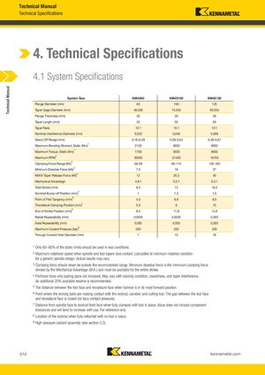
Технические характеристики
Характеристики системы
| Параметр | KM4X63 | KM4X100 | KM4X125 |
|---|---|---|---|
| Диаметр фланца (мм) | 63 | 100 | 125 |
| Диаметр по калибровочной линии конуса (мм) | 48,026 | 75,043 | 95,054 |
| Толщина фланца (мм) | 25 | 29 | 29 |
| Длина конуса (мм) | 32 | 50 | 63 |
| Соотношение конуса | 10:1 | 10:1 | 10:1 |
| Номинальный диаметр интерференции (мм) | 0,022 | 0,046 | 0,058 |
| Диапазон отстояния (мм) | 0,16–0,28 | 0,38–0,54 | 0,49–0,67 |
| Максимальный момент изгиба статический (Нм)¹ | 2100 | 6000 | 9000 |
| Максимальный крутящий момент статический (Нм)¹ | 1700 | 5500 | 8000 |
| Максимальные обороты² | 30000 | 21400 | 16700 |
| Диапазон силы зажима (кН)³ | 36–58 | 90–110 | 135–165 |
| Минимальная сила вытяжного стержня (кН)³ | 7,5 | 18 | 27 |
| Сила отпуска конуса KM4X (кН)⁴ | 12 | 25,3 | 40 |
| Механическое преимущество | 4,8:1 | 5,0:1 | 5,0:1 |
| Общий ход (мм) | 9,5 | 13 | 16,3 |
| Номинальное положение отталкивания (мм)⁵ | 1 | 1,2 | 1,5 |
| Точка первого касания (мм)⁶ | 4,0 | 6,8 | 8,5 |
| Теоретическое положение зажима (мм)⁷ | 5,0 | 8 | 10 |
| Положение конца хода (мм)⁸ | 8,5 | 11,8 | 14,8 |
| Повторяемость в радиальном направлении (мм) | 0,0025 | 0,0025 | 0,003 |
| Повторяемость в осевом направлении (мм) | 0,002 | 0,002 | 0,002 |
| Максимальное давление охлаждающей жидкости (бар)⁹ | 200 | 200 | 200 |
| Диаметр сквозного отверстия охлаждающей жидкости (мм) | 7 | 10 | 16 |
Примечания:
- В реальных условиях должны использоваться только 60–80% от статических пределов.
- Максимальная скорость вращения при потере контакта между конусом шпинделя и инструмента, рассчитанная при минимальном допуске материала для универсальной конструкции шпинделя. Фактические результаты могут варьироваться.
- Сила зажима никогда не должна выходить за пределы рекомендуемого диапазона. Минимальная сила вытяжного стержня является минимальной силой зажима, разделённой на механическое преимущество и должна быть доступна для всего хода.
- Только сила трения (пакет пружин не включён). Может варьироваться в зависимости от условий смазываемости, чистоты и интерференции конуса. Рекомендуется дополнительный запас 20%.
- Расстояние между передней гранью инструмента и гранью приёмника при перемещении направляющего стержня в его самое передовое положение.
- Точка, где блокирующие шары контактируют с направляющим стержнем, контейнером и режущим инструментом. Зазор между передней гранью инструмента и гранью приёмника закрыт (без контактного давления на грань).
- Расстояние от грани шпинделя до передней грани направляющего стержня при полном зажиме с установленным инструментом. Это значение не включает допуски компонентов и будет иметь тенденцию к увеличению при использовании. Только для справки.
- Положение направляющего стержня при полном втягивании без инструмента на месте.
- Узел охлаждающей жидкости высокого давления (см. раздел 3.2).