Модульные инструментальные системы линейки KM4X Kennametal 2017 - страница 118
Навигация
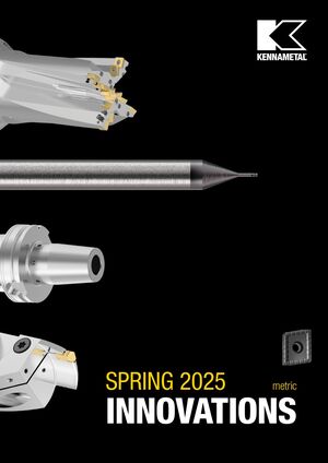 Новинки Kennametal - весна 2025
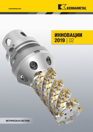 Каталог Kennametal инновации 2019.2
 Инновационные токарные пластины с покрытиями KENGold CVD и PVD Kennametal 2025
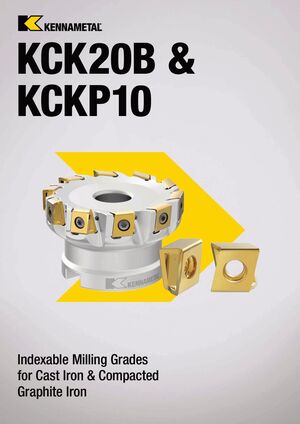 Сменные фрезерные пластины сплавов KCK20B и KCKP10 Kennametal 2024
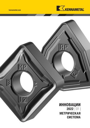 Каталог Kennametal инновации 2022.1
 Каталог Kennametal инновации 2020.2
- __KMT_KM4X_COVER_EN_Covers_EN_in
- KMT_KM4X_Catalog_A000_A001_EN
- KMT_KM4X_Catalog_A002_A003_EN
- KMT_KM4X_Catalog_A004_A005_EN
- KMT_KM4X_Catalog_A006_A007_EN
- KMT_KM4X_Catalog_A008_A009_EN
- KMT_KM4X_Catalog_A010_A011_EN
- KMT_KM4X_Catalog_B000_B001_EN
- KMT_KM4X_Catalog_B002_B003_EN
- KMT_KM4X_Catalog_B004_B005_EN
- KMT_KM4X_Catalog_B006_B007_EN
- KMT_KM4X_Catalog_B008_B009_EN
- KMT_KM4X_Catalog_B010_B011_EN
- KMT_KM4X_Catalog_B012_B013_EN
- KMT_KM4X_Catalog_B014_B015_EN
- KMT_KM4X_Catalog_B016_B017_EN
- KMT_KM4X_Catalog_B018_B019_EN
- KMT_KM4X_Catalog_B020_B021_EN
- KMT_KM4X_Catalog_B022_B023_EN
- KMT_KM4X_Catalog_B024_B025_EN
- KMT_KM4X_Catalog_B026_B027_EN
- KMT_KM4X_Catalog_B028_B029_EN
- KMT_KM4X_Catalog_B030_B031_EN
- KMT_KM4X_Catalog_B032_B033_EN
- KMT_KM4X_Catalog_B034_B035_EN
- KMT_KM4X_Catalog_B036_B037_EN
- KMT_KM4X_Catalog_B038_B039_EN
- KMT_KM4X_Catalog_B040_B041_EN
- KMT_KM4X_Catalog_B042_B043_EN
- KMT_KM4X_Catalog_B044_B045_EN
- KMT_KM4X_Catalog_B046_B047_EN
- KMT_KM4X_Catalog_B048_B049_EN
- KMT_KM4X_Catalog_B050_B051_EN
- KMT_KM4X_Catalog_B052_B053_EN
- KMT_KM4X_Catalog_B054_B055_EN
- KMT_KM4X_Catalog_B056_B057_EN
- KMT_KM4X_Catalog_B058_B059_EN
- KMT_KM4X_Catalog_B060_B061_EN
- KMT_KM4X_Catalog_B062_B063_EN
- KMT_KM4X_Catalog_B064_B065_EN
- KMT_KM4X_Catalog_B066_B067_EN
- KMT_KM4X_Catalog_B068_B069_EN
- KMT_KM4X_Catalog_B070_B071_EN
- KMT_KM4X_Catalog_B072_B073_EN
- KMT_KM4X_Catalog_B074_B075_EN
- KMT_KM4X_Catalog_B076_B077_EN
- KMT_KM4X_Catalog_B078_B079_EN
- KMT_KM4X_Catalog_B080_B081_EN
- KMT_KM4X_Catalog_B082_B083_EN
- KMT_KM4X_Catalog_B084_B085_EN
- KMT_KM4X_Catalog_C000_C001_EN
- KMT_KM4X_Catalog_C002_C003_EN
- KMT_KM4X_Catalog_C004_C005_EN
- KMT_KM4X_Catalog_C006_C007_EN
- KMT_KM4X_Catalog_C008_C009_EN
- KMT_KM4X_Catalog_C010_C011_EN
- KMT_KM4X_Catalog_C012_C013_EN
- KMT_KM4X_Catalog_C014_C015_EN
- KMT_KM4X_Catalog_C016_C017_EN
- KMT_KM4X_Catalog_C018_C019_EN
- KMT_KM4X_Catalog_C020_C021_EN
- KMT_KM4X_Catalog_C022_C023_EN
- KMT_KM4X_Catalog_C024_C025_EN
- KMT_KM4X_Catalog_C026_C027_EN
- KMT_KM4X_Catalog_C028_C029_EN
- KMT_KM4X_Catalog_C030_C031_EN
- KMT_KM4X_Catalog_C032_C033_EN
- KMT_KM4X_Catalog_C034_C035_EN
- KMT_KM4X_Catalog_C036_C037_EN
- KMT_KM4X_Catalog_C038_C039_EN
- KMT_KM4X_Catalog_C040_EN
- __KMT_KM4X_COVER_EN_Covers_EN_in
Проектирование пакета пружин
Выбор пружин должен следовать основным рекомендациям ниже:
- Используйте наибольший возможный диаметр, чтобы увеличить усталостную долговечность и уменьшить длину пакета пружин.
- Для данного диаметра и толщины дисковой пружины более длинный стек обеспечивает более долгий срок службы.
- Параллельная укладка (наборы пружин в серии) позволяет получить более компактные пакеты пружин и большую силу пружины; однако между пружинами вводится коэффициент трения.
- Максимальное количество пружин, уложенных параллельно, должно быть три, если не указано иное.
- Большее количество наборов снижает силу пакета пружин при отпуске инструмента.
- Сила пакета пружин в положении «зажато без инструмента» должна быть больше или равна минимальной силе зажима, разделённой на механическое преимущество.
- Сила пакета пружин в зажатом положении должна быть больше или равна номинальной силе зажима, разделённой на механическое преимущество.
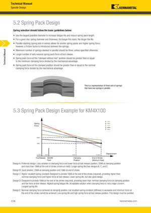
На рисунке показана конфигурация трёх наборов пружин с двумя пружинами параллельно.
Пример проектирования пакета пружин для KM4X100
Диаграмма показывает различные конструкции (A–E) пакета пружин с отмеченными критическими позициями: отпуск инструмента (–1,2 мм), грань шпинделя (0 мм), положение зажима (8 мм) и конец хода (11,8 мм).
Конструкция A (предпочтительная): Меньше вариаций силы зажима и меньше силы при отпуске инструмента; 20 кН при зажиме и более 18 кН в конце хода. Более долгий срок службы пружин, чем конструкции B, C и E.
Конструкция B (хорошее решение): 20 кН при зажиме и 18 кН в конце хода.
Конструкция C (повышенная жёсткость): Разработана для обеспечения 18 кН в конце хода (требуемое), обеспечивая более высокую номинальную силу зажима и более высокую силу при отпуске. Меньший срок службы пружин, но также хорошая конструкция.
Конструкция D: Разработана для обеспечения 18 кН в конце хода (требуемое), обеспечивая меньшую номинальную силу зажима и малую силу при отпуске. Наибольший срок службы пружин. Приемлемое решение, когда сила зажима не является основной проблемой.
Конструкция E (избегать): Номинальная сила зажима достигается в зажатом положении, но результирующая жёсткость пружины избыточна и минимальную силу в конце хода достичь невозможно. Низкий срок службы пружин и высокая сила при отпуске. Эту конструкцию необходимо избегать.