Модульные инструментальные системы линейки KM4X Kennametal 2017 - страница 124
Навигация
 Новинки Kennametal - весна 2025
 Каталог Kennametal инновации 2019.2
 Инновационные токарные пластины с покрытиями KENGold CVD и PVD Kennametal 2025
 Сменные фрезерные пластины сплавов KCK20B и KCKP10 Kennametal 2024
 Каталог Kennametal инновации 2022.1
 Каталог Kennametal инновации 2020.2
- __KMT_KM4X_COVER_EN_Covers_EN_in
- KMT_KM4X_Catalog_A000_A001_EN
- KMT_KM4X_Catalog_A002_A003_EN
- KMT_KM4X_Catalog_A004_A005_EN
- KMT_KM4X_Catalog_A006_A007_EN
- KMT_KM4X_Catalog_A008_A009_EN
- KMT_KM4X_Catalog_A010_A011_EN
- KMT_KM4X_Catalog_B000_B001_EN
- KMT_KM4X_Catalog_B002_B003_EN
- KMT_KM4X_Catalog_B004_B005_EN
- KMT_KM4X_Catalog_B006_B007_EN
- KMT_KM4X_Catalog_B008_B009_EN
- KMT_KM4X_Catalog_B010_B011_EN
- KMT_KM4X_Catalog_B012_B013_EN
- KMT_KM4X_Catalog_B014_B015_EN
- KMT_KM4X_Catalog_B016_B017_EN
- KMT_KM4X_Catalog_B018_B019_EN
- KMT_KM4X_Catalog_B020_B021_EN
- KMT_KM4X_Catalog_B022_B023_EN
- KMT_KM4X_Catalog_B024_B025_EN
- KMT_KM4X_Catalog_B026_B027_EN
- KMT_KM4X_Catalog_B028_B029_EN
- KMT_KM4X_Catalog_B030_B031_EN
- KMT_KM4X_Catalog_B032_B033_EN
- KMT_KM4X_Catalog_B034_B035_EN
- KMT_KM4X_Catalog_B036_B037_EN
- KMT_KM4X_Catalog_B038_B039_EN
- KMT_KM4X_Catalog_B040_B041_EN
- KMT_KM4X_Catalog_B042_B043_EN
- KMT_KM4X_Catalog_B044_B045_EN
- KMT_KM4X_Catalog_B046_B047_EN
- KMT_KM4X_Catalog_B048_B049_EN
- KMT_KM4X_Catalog_B050_B051_EN
- KMT_KM4X_Catalog_B052_B053_EN
- KMT_KM4X_Catalog_B054_B055_EN
- KMT_KM4X_Catalog_B056_B057_EN
- KMT_KM4X_Catalog_B058_B059_EN
- KMT_KM4X_Catalog_B060_B061_EN
- KMT_KM4X_Catalog_B062_B063_EN
- KMT_KM4X_Catalog_B064_B065_EN
- KMT_KM4X_Catalog_B066_B067_EN
- KMT_KM4X_Catalog_B068_B069_EN
- KMT_KM4X_Catalog_B070_B071_EN
- KMT_KM4X_Catalog_B072_B073_EN
- KMT_KM4X_Catalog_B074_B075_EN
- KMT_KM4X_Catalog_B076_B077_EN
- KMT_KM4X_Catalog_B078_B079_EN
- KMT_KM4X_Catalog_B080_B081_EN
- KMT_KM4X_Catalog_B082_B083_EN
- KMT_KM4X_Catalog_B084_B085_EN
- KMT_KM4X_Catalog_C000_C001_EN
- KMT_KM4X_Catalog_C002_C003_EN
- KMT_KM4X_Catalog_C004_C005_EN
- KMT_KM4X_Catalog_C006_C007_EN
- KMT_KM4X_Catalog_C008_C009_EN
- KMT_KM4X_Catalog_C010_C011_EN
- KMT_KM4X_Catalog_C012_C013_EN
- KMT_KM4X_Catalog_C014_C015_EN
- KMT_KM4X_Catalog_C016_C017_EN
- KMT_KM4X_Catalog_C018_C019_EN
- KMT_KM4X_Catalog_C020_C021_EN
- KMT_KM4X_Catalog_C022_C023_EN
- KMT_KM4X_Catalog_C024_C025_EN
- KMT_KM4X_Catalog_C026_C027_EN
- KMT_KM4X_Catalog_C028_C029_EN
- KMT_KM4X_Catalog_C030_C031_EN
- KMT_KM4X_Catalog_C032_C033_EN
- KMT_KM4X_Catalog_C034_C035_EN
- KMT_KM4X_Catalog_C036_C037_EN
- KMT_KM4X_Catalog_C038_C039_EN
- KMT_KM4X_Catalog_C040_EN
- __KMT_KM4X_COVER_EN_Covers_EN_in
6.2 Установка — продолжение
14. Если положение зажима неприемлемо, необходимо отрегулировать положение канистра «A». Для этого снимите компоненты зажима (см. раздел 6.2). Если резьбовой стержень зажимает на расстояние больше максимума, необходимо удалить материал из канистра, чтобы переместить канистр дальше в шпиндель. Если резьбовой стержень зажимает на расстояние меньше минимума, требуется прокладка для перемещения канистра к торцу шпинделя. На диаграмме ниже показано приблизительное изменение положения зажима при изменении толщины прокладки на 0,1 мм. После внесения изменений переберите и повторите измерения. Листовой материал прокладки можно подшлифовать до пользовательской толщины.
| Размер системы | Изменение положения зажима* (мм) | Номер заказа прокладки |
|---|---|---|
| KM4X63 | 0,85 | 5701914 |
| KM4X100 | 1,00 | 5413745 |
| KM4X125 | 1,00 | 5635360 |
* Изменение положения зажима резьбового стержня при изменении толщины прокладки на 0,1 мм.
15. С зажатой пробкой используйте шестигранный ключ (размер 5 мм для KM4X63, 8 мм для KM4X100 и 10 мм для KM4X125), чтобы затянуть установочный винт резьбового стержня.
| Размер системы | Размер шестигранника (мм) | Крутящий момент (Нм) |
|---|---|---|
| KM4X63 | 5,00 | 25,00 |
| KM4X100 | 8,00 | 50,00 |
| KM4X125 | 10,00 | 75,00 |
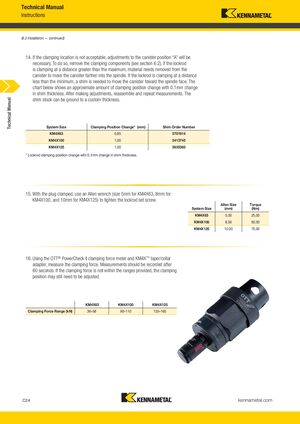
16. Используя динамометр зажимной силы OTT® PowerCheck II и адаптер конуса/муфты KM4X™, измерьте силу зажима. Измерения должны быть записаны через 60 секунд. Если сила зажима не находится в указанных диапазонах, положение зажима может по-прежнему требовать регулировки.
| Диапазон силы зажима (кН) | KM4X63 | KM4X100 | KM4X125 |
|---|---|---|---|
| 36–58 | 90–110 | 135–165 |