Общий каталог Tungaloy 2020 - 2021 - страница 896
Навигация
 Брошюра Tungaloy новая продукция
 Каталог Tungaloy глубокое сверление 1
 Каталог Tungaloy инструмент для автоматов швейцарского типа
 Каталог Tungaloy зубофрезерование
 Каталог Tungaloy глубокое сверление 2
- A Grade
- Grade contents
- CVD - Coated Grade
- PVD - Coated Grade
- Ceramic
- Cermet
- CBN
- PCD (T-DIA)
- Uncoated Cemented Carbide
- Grade - Comparison Chart
- CVD Coated Grades for Turning
- PVD Coated Grade for Turning
- Cermet for Turning
- Cemented Carbide for Turning
- PCBN and PCD for Turning
- Ceramics for Turning
- CVD Coated Grade for Milling
- PVD Coated Grade for Milling
- Cermet for Milling
- Cemented Carbide for Milling
- PCBN and PCD for Milling
- Ceramics for Milling
- Chipbreaker Comparison Chart
- Negative insert type
- Positive insert type
- B Insert
- Insert - Content structure
- Insert Contents
- General insert for Turning
- Designation system for Insert
- Chipbreaker Guide
- Negative - Steel
- Negative - Stainless Steel
- Negative - Cast Iron
- Negative - Non-ferrous Metal
- Negative - Superalloys and titanium
- Negative - Hard Materials
- Positive - Steel
- Positive - Stainless Steel
- Positive - Cast Iron
- Positive - Non-ferrous Metal
- Positive- Superalloys and titanium
- Positive - Hard Materials
- Chipbreaker Overview
- Negative type with hole
- Negative type without hole
- Positive 7° with hole
- Positive 11° with hole
- Positive 7° with hole
- Positive 5° with hole
- Positive 11° without hole
- Double-sided positive type with hole
- Positive 7° without hole
- Negative
- CN
- DN
- RN
- SN
- TN
- VN
- WN
- YN
- KN
- HN
- Positive
- CC
- CP
- DC
- DP
- DX
- EP
- RC
- RT
- SC
- SP
- TC
- TP
- VB
- VC
- VP
- WP
- VX
- WB
- WX
- YW
- JXF
- JXR
- JXB
- JTB
- J10E
- 10E
- CBN
- Features
- BXA20
- WavyJoint
- GNGA type CBN
- HP Chipbreaker
- Designation System for T-CBN (PCBN) Inserts
- Negative type
- Positive type
- PCD
- Negative type
- Positive type
- Technical Guide
- T-CBN series for hardened steel and hard material
- T-CBN series for sintered metal
- T-CBN series for grey cast iron and ductile cast iron
- T-CBN Series - Honing specifications
- Features - PCD grade, T-DIA series
- C External Toolholder
- External Toolholder - Content structure
- Main products
- Designation system for Toolholders
- Quick Guide
- Negative type
- Positive type
- Features
- TurnTen-Feed
- ISO-EcoTurn
- Cutting edge
- L
- J
- N
- V
- P
- A
- G
- B
- R
- X
- D
- S
- K
- F
- Q
- H
- Special
- Technical Guide
- Parts for coolant hose
- FixRTurn - Standard cutting conditions
- MiniForce-Turn - Standard cutting conditions
- TurnTen-Feed - Standard cutting conditions
- TurnFeed - Standard cutting conditions
- TurnTec - Standard cutting conditions
- DimpleFX - Standard cutting conditions
- D Internal Toolholder
- Internal Toolholder - Content structure
- Main products
- Designation system for Toolholders
- Quick Guide
- Positive type
- Negative type
- Features
- BoreMeister
- StreamJetBar
- Cutting edge
- L
- X
- J
- K
- F
- U
- Q
- Z
- Others
- Technical Guide
- Sleeves for StreamJetBar
- MiniForce-Turn - Standard cutting conditions
- TurnTec - Standard cutting conditions
- E Threading tool
- Threading Tool - Content structure
- Main products
- Quick Guide - Applicable tool
- External threading
- Internal threading
- Features
- TetraMini-Cut
- DuoJust-Cut
- Insert for threading
- For Energy
- API Round
- API Round (For tool-rotating machines)
- API Buttress
- API Buttress (For tool-rotating machines)
- General
- 60° thread angle
- 55° thread angle (General purpose)
- ISO metric (General purpose)
- Unified (General purpose)
- For Pipe
- Whitworth, Parallel pipe thread
- BSPT (for Pipe)
- NPT (for Pipe)
- NPTF
- For Machine parts
- 30° Trapezoidal / DIN103
- Round / DIN405
- For Aerospace industry
- UNJ
- MJ
- For Machine parts, Pipe
- 29° Trapezoidal / ACME
- 29° Trapezoidal/ STUB ACME
- Toolholder for threading
- Technical Guide
- Designation system for TT-type insert
- Designation system for ST-type insert
- TungThread - Standard cutting conditions
- TungT-Clamp - Standard cutting conditions
- TetraMini-Cut - Standard cutting conditions
- DuoJust-Cut - Standard cutting conditions
- TinyMini-Turn - Standard cutting conditions
- Replacement of shim
- F Parting, Grooving
- Parting, Grooving - Content structure
- Par ting, Grooving - Machining Overview
- Quick Guide
- Features
- TungCut
- External grooving
- TungCut
- TetraMini-Cut
- TetraForce-Cut
- My-T Series
- Toolholder for 2 corner insert
- Toolholder for 1 corner insert
- 2 corner insert
- Standard cutting conditions
- Chipbreaker Guide
- 1 corner insert
- Chipbreaker Guide
- Standard cutting contions
- TungT-Clamp
- Standard cutting conditions
- Insert
- Applicable toolhoder for GTGN type insert
- GTGN type insert
- Standard cutting conditions
- TungHeavyGroove
- Chipbreaker Guide
- Insert
- Standard cutting conditions
- Others
- Internal grooving
- TungCut
- Insert
- Chipbreaker Guide
- Standard cutting conditions
- My-T Series
- Insert
- Chipbreaker Guide
- Standard cutting conditions
- TungT-Clamp
- Insert
- Standard cutting conditons
- Applicable toolhoder for GTGN type insert
- GTGN type insert
- Standard cutting conditions
- Others
- Face grooving
- EasyMulti-Cut
- Chipbreaker Guide
- Insert
- Standard cutting conditions
- TungCut
- Insert
- Chipbreaker Guide
- Standard cutting conditions
- My-T Series
- Insert
- Chipbreaker Guide
- Standard cutting conditions
- Others
- Grooving and parting
- TungCut
- Insert
- Chipbreaker Guide
- Standard cutting conditions
- My-T Series
- Toolholder for 2 corner insert
- Insert
- Standard cutting conditions
- Chipbreaker Guide
- Toolhoder for 1 corner insert
- Insert
- Chipbreaker Guide
- Standard cutting conditions
- Undercutting, profiling
- TungCut
- Insert
- Standard cutting conditions
- Chipbreaker Guide
- Technical guide
- Parts for coolant hose
- G Miniature Machining
- Miniature Machining - Content structure
- Main products
- Quick Guide
- Miniature External Turning
- Miniature Internal Turning
- Miniature Grooving
- Miniature Parting
- Miniature Threading
- Miniature Internal Turning - TinyMini-Turn
- Features
- TungTurn-Jet
- DirectTung-Jet system
- MiniForce-Turn
- External turning
- L
- J, U
- N
- P
- A
- G
- D
- F
- X
- Others
- Technical Guide
- MiniForce-Turn - Standard cutting conditions
- J-Seires - Standard cutting conditions
- TinyMini-Turn
- Internal turning
- Internal thrading
- Internal grooving
- Face grooving
- Standard cutting conditions
- Grooving
- TetraMini-Cut
- Insert
- Standard cutting conditions
- TetraForce-Cut
- Insert
- Standard cutting coditions
- J-Series
- Applicable toolholder for JTG insert
- Insert - JTG
- Standard cutting conditions
- Applicatble toolholder for JXG insert
- Insert - JXG
- Applicable toolholder for JVG insert
- Insert - JVG
- JXG, JVG - Standard cutting conditions
- TungHeavyGroove
- Insert
- Standard cutting conditions
- Threading
- TungThread
- J-Series
- Insert - JXT
- Insert - JTT
- Standard cutting conditions
- Parting
- DuoJust-Cut
- Insert
- Standard cutting conditions
- TungCut
- Chipbreaker Guide
- Insert
- Standard cutting conditions
- H Milling Cutter
- Milling Cutter - Content structure
- Designation system
- Designation system for Inser t
- Application Overview
- Quick Guide
- High-Feed Milling
- Face Milling
- Shoulder milling
- Slot milling
- Profile milling
- Thread milling
- High FeedMilling
- Features
- DoFeed
- TungForce-Feed
- TungForce-Feed
- Insert
- Standard cutting conditions
- DoFeed 03
- Insert
- Standard cutting conditions
- DoFeed 06
- Insert
- Standard cutting conditions
- DoTwistBall
- Insert
- Standard cutting conditions
- DoFeedQuad
- Insert
- Standard cutting conditions
- MillQuadFeed
- Insert
- Standard cutiing conditions
- MillFeed
- Insert
- Standard cutting conditions
- Face Milling
- Features
- TungSpeed-Mill
- DoTriple-Mill
- Insert
- Standard cittiong conditions
- DoOcto
- Insert
- Standard cittiong conditions
- DoQuad-Mill
- Insert
- Standard cittiong conditions
- DoPent
- Insert
- Standard cittiong conditions
- TungMill - TAW/EAW
- Insert
- Standard cittiong conditions
- TungSpeed-Mill - TPYP/EPYP
- Insert
- Standard cittiong conditions
- TungSpeed-Mill - TPYD/EPYD
- Insert
- Standard cittiong conditions
- TungMill - TFE/EFE
- Insert
- Standard cittiong conditions
- TungMill - DPD/EDPD
- Insert
- Standard cutting conditions
- Other tools
- S-TAQ system
- QC system for TAC Mills
- Shoulder milling
- Features
- DoForce-Tri
- Tung-Tri
- DoForce-Tri
- Insert
- Standard cutting conditions
- Tung-Tri
- Insert
- Standard cutting conditions
- TungTri-Shred
- Insert
- Standard cutting conditions
- TungForce-Rec
- Insert
- Standard cutting conditions
- TungRec 07
- Insert
- Standard cutting conditions
- TungRec 11
- Insert
- Standard cutting conditions
- TungRec 18
- Insert
- Standard cutting conditions
- TungQuad
- Insert
- Standard cutting conditions
- TungMill - TPW-EPW
- Insert
- Standard cutting conditions
- DoRec
- Insert
- Standard cutting conditions
- TecMill
- Insert
- Standard cutting conditions
- TungAlu-Mill
- Insert
- Standard cutting conditions
- Other tools
- Slot Milling
- Features
- TungUniversalSlot
- Insert
- Standard cutting conditions
- TungThinSlit
- Insert
- Standard cutting conditions
- TungUniversalSlot
- Insert
- Standard cutting conditions
- TecTangentialSlot
- Insert
- Standard cutting conditions
- Profile Milling
- Features
- ProfileMill series
- BallFinishNose
- BallRoughNose
- Insert
- Standard cutting conditions
- BallFinishNose
- Insert
- Standard cutting conditions
- DoMini-Mill
- Insert
- Standard cutting conditions
- FixRMill
- Insert
- Standard cutting conditions
- RoundSplit
- Insert
- Standard cutting conditions
- Other tools
- I Endmill
- EndMill - Content structure
- Main products
- Solid Endmill
- Quick Guide
- Designation system
- Features
- Square
- VariableMeister
- Standard cuting conditions
- FinishMeistrer / ShredMeister
- Standard cutting conditions
- SolidMeister
- Standard cutting conditions
- Continuation of SolidMeister
- Standard cutting conditions
- High feed
- FeedMiester
- Standard cutting conditions
- Ball
- Standard cutting conditions
- Exchangeable Endmill
- TungMeister
- Quick Guide
- Features
- Designation system
- Square
- Standard cutting conditions
- Radius
- VRB, VRC, VRD
- Standard cutting conditions
- VFX
- Standard cutting conditions
- Ball
- Standard cutting conditions
- Spot drilling
- Standard cutting conditions
- Counterboring
- Standard cutting conditions
- Chamfering
- Staandard cutting conditions
- Slotting
- Standard cutting conditions
- Shank
- Other tools
- Threading endmill
- Features
- Solid carbide endmill - SolidThread
- Designation System
- ISO metric
- Unified
- Whitworth
- BSPT
- NPT
- NPTF
- MJ
- UNJ
- Standard cutting conditions
- TungMeister
- Designation System
- ISO metric
- Unified
- Whitwor th
- 60° par tial profile
- 55° par tial profile
- Standard cutting conditions
- ETTL
- Standard cutting conditions
- Other tools
- Milling insert
- J Drilling Tool
- Drilling Tool - Content structure
- Main product
- Basic Selection of Drilling Tools
- Quick Guide
- General drilling
- Deep drilling
- 2 Effective Drill
- DrillMeister
- Features
- TID L/D=1.5
- TID L/D=3
- TID L/D=5
- TID L/D=8
- TID L/D=12
- TIDC L/D=3
- TIDC L/D=5
- Chamfering adapter
- Drill head
- DMP General purpose
- DMC High precision machining
- Standard cutting conditions
- DrillForce-Meister
- Drill head
- Standard cutting coditions
- Regrinding holder
- SolidDrill
- Quick Guide
- DSW
- DSW-DE3 L/D=3
- DSW-DE5 L/D=5
- DSW-DI5 L/D=5
- DSW-DI8 L/D=8
- Designation system
- Standard cutting coditions
- DSX
- DSX-F03 L/D=3
- DSX-F05 L/D=5
- DSX-F08 L/D=8
- Standard cutting conditions
- DSE
- DSE-F02 L/D=2
- DSE-F03 L/D=3
- Standard cutting conditions
- DSM
- Standard cutting conditions
- DSM-CP
- Standard cutting conditions
- FDC-S
- L/D=5
- L/D=8
- Standard cutting conditions
- CDS
- Standard cutting cnditions
- Indexable drill
- TungSix-Drill
- Features
- L/D=2
- L/D=3
- L/D=4
- Standard cutting conditions
- Insert
- Chamfering tool
- TungDrillTwisted
- L/D=2
- L/D=3
- L/D=4
- L/D=5
- Insert
- Standard cutting conditions
- Chamfering tool
- EZ sleeve
- TundDrillBig
- TDB, TDS cartridge set
- Insert
- Standard cutting conditions
- TDB, TDX cartridge set
- Insert
- Standard cutting conditions
- TDP
- Insert
- Standard cutting conditions
- Drilling Insert
- Deep Hole Drill
- Indexable Gundrill guide
- DeepTri-Drill
- Features
- MCTR L/D=10
- MCTR L/D=15
- MCTR L/D=20
- MCTR L/D=25
- MCTRCH L/D=25
- MCTR L/D=8
- MCTR L/D=10
- MCTR L/D=15
- MCTR L/D=25
- TRLG
- TRLGCH
- TRLG-F
- Insert
- Guide pad
- Standard cutting conditions
- SLJ
- Standard cutting conditions
- BTA tool
- Drill Head Category
- Drill Tube Category
- Tri-Fine
- Insert
- Guide pad
- Fine-Beam
- Insert
- Guide pad
- Unidex
- Insert
- Standard cutting conditions
- Brazed drill head
- Standard cutting conditions
- Drill tube
- HF drill
- K Tooling System
- Tooling System - Content structure
- Main products
- TungCap
- Features
- TungCap tooling system
- External turning
- L
- J
- N
- V
- Internal turning
- L
- U
- X
- Q
- Treading
- Grooving
- Drilling
- Milling
- Adapter
- Side-lock holder
- SwissBore
- Features
- Boring head / Boring bar
- Digital display unit
- Clamping units
- Nomenclature for clamping units
- Clamping units & tools for CNC lathes
- Clamping torque
- TungHold
- DIN69871
- DIN 69893 HSK
- BT MAS 403
- DIN2080
- Other holders
- TungFit adapter
- ER Collet Chucking System
- ER collet
- TungShrink, ER collet type
- TungShrink - Induction heating unit for shrink tool chucking
- TungShrink - Quick change type
- Tapping attachment for ER collet chuck holders
- Pull stud with JIN/ANSI retention knob (BT), for MAZAK machines
- Parts
- Easy Lock - Electrical nut-clamp torque control device
- SpinJet
- Wireless RPM speed display
- Collet
- BeamWrench
- SwissBore
- Wide range of variation quick change system
- Digital display unit
- Boring head / boring bar
- Adapter
- PINZBOHR®
- Features
- System
- Designation System
- Boring head
- Arbor
- Adapter
- Parts
- Cartridge
- List of ISO Standard Cartridges by Application
- A-type (Positive rake, compact type)
- Top-Borer Tool
- Boring bar tool
- L User’s Guide
- User´s guide - contents
- Parts for Tools
- Screws
- Shims
- Clamps
- Clamp Sets
- Levers
- Pins
- Chipbreaker Pieces
- Springs (Springs for Shims)
- Coolant Supply Attachment
- Sizing Plates
- Washers
- Locators
- Insert locking wedges
- Locator adjusting wedges
- Fine adjusting screws
- Cover
- Technical Reference
- Turning Tools
- Grooving and Parting Tools
- Threading Tools
- Thread Milling CNC Program for Internal Thread
- Milling Tools
- Endmills
- Drilling Tools
- Symbols of Metals
- Approximate Conversion Table of Hardness
- Surface Roughness
- GC_2020-2021_G_M_Index
- Numeric
- A
- B
- C
- D
- E
- F
- G
- H
- I
- J
- K
- L
- M
- N
- O
- P
- Q
- R
- S
- T
- U
- V
- W
- X
- Y
- Z
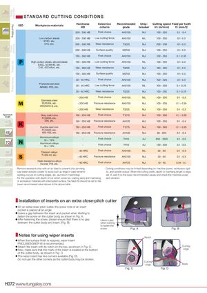
Profile MillingSlot MillingShoulderMillingFace MillingHigh FeedMilling S TA N D A R D CUTTING CONDITIONS ISO Workpiece materials Hardness Selection Recommended Chip- Cutting speed Feed per toothHBcriteriagradebreakerVc (m/min)fz (mm/t) 200 - 300 HB First choice AH3135 MJ 100 - 250 0.1 - 0.4 Low carbon steels 200 - 300 HB Low cutting force AH3135 ML 100 - 250 0.1- 0.3 S15C, etc. C15, etc. 200 - 300 HB Wear resistance T3225 MJ 200 - 350 0.1- 0.3 200 - 300 HB Surface quality NS740 MJ 100 - 250 0.1- 0.3 150 - 300 HB First choice AH3135 MJ 100 - 250 0.1- 0.35 High carbon steels, alloyed steels 150 - 300 HB Low cutting force AH3135 ML 100 - 250 0.1- 0.3 S45C, SCM440, etc. C45, 42CrMo4, etc. 150 - 300 HB Wear resistance T3225 MJ 180 - 300 0.1- 0.3 150 - 300 HB Surface quality NS740 MJ 100 - 250 0.1- 0.3 30 - 40 HRC First choice AH3135 MJ 100 - 200 0.1- 0.3 Prehardened steelNAK80, PX5, etc. 30 - 40 HRC Low cutting force AH3135 ML 100 - 200 0.1- 0.25 30 - 40 HRC Wear resistance T3225 MJ 150 - 250 0.1- 0.25 - 200 HB First choice AH3135 ML 100 - 200 0.1 - 0.3 Stainless steel SUS304, etc. - 200 HB Fracture resistance AH3135 MJ 100 - 200 0.1 - 0.35 X5CrNi18-9, etc. - 200 HB Wear resistance T3225 MJ 100 - 250 0.1 - 0.3 Approachangle Grey cast irons 150 - 250 HB First choice T1215 MJ 100 - 300 0.1 - 0.35FCD400, etc. 10°-20° 250, etc. 150 - 250 HB Fracture resistance AH120 MJ 100 - 250 0.1 - 0.4 Ductile cast iron 150 - 250 HB First choice T1215 MJ 100 - 300 0.1 - 0.35 45° FCD400, etc.400-15S, etc. 150 - 250 HB Fracture resistance AH120 MJ 80 - 200 0.1 - 0.4 70° Aluminium alloysSi < 13% - First choice TH10 AJ 500 - 1500 0.1 - 0.5Aluminium alloysSi ≥ 13%-First choiceTH10AJ150 - 5000.1 - 0.5 85° Titanium alloys - 40 HRC First choice AH3135 ML 30 - 60 0.1 - 0.3 Ti-6Al-4V, etc. - 40 HRC Fracture resistance AH3135 MJ 30 - 60 0.1 - 0.3 88° Heat-resistance alloysInconel 718, etc.- 40 HRC First choice AH725 MJ 10 - 40 0.04 - 0.1 · Remove excessive chip with an air blast to prevent chip jamming. · Cutting conditions may be limited depending on machine power, workpiece rigid- 90° · Use water-soluble coolant to avoid built-up edge in case extreme ity, and spindle output. When the cutting width, depth or overhang length is large, welding occurs on cutting edges. (ex. aluminium machining). set Vc and fz to the lower recommended values and check the machine power · For the operation with depth of cut which varies (ex. casting skin) and machining and vibration. Others of workpiece materials with interrupted surface, the feed (fz) should be set to the lower recommened value shown in the above table. Installation of inserts on an extra close-pitch cutter • On an extra close-pitch cutter, the screw hole of an insert pocket is placed at an angle. • Leave a gap between the insert and pocket when starting to fasten the screw on the cutter body as shown in Fig. A. • After fastening the screw, please ensure that there is no gap Leave a gap between the cutter body and insert. (Fig. B) when starting to fasten the screw. Fig. A Fig. B Notes for using wiper inserts Notch • When fine surface finish is required, wiper insert PNCU0905GNER-W is recommended. • Attach the insert with its notch on the top, as shown in Fig. C. Cutting • Also, make sure that the mark of the insert is located at the bottom edge of the cutter body, as shown in Fig. D. • The wiper insert has two corners available (Fig. D). Do not use the other corners as the cutter body may be broken. Cutting edge Mark Fig. C Fig. D H072 www.tungaloy.com