Общий каталог Tungaloy 2020 - 2021 - страница 858
Навигация
 Брошюра Tungaloy новая продукция
 Каталог Tungaloy глубокое сверление 1
 Каталог Tungaloy инструмент для автоматов швейцарского типа
 Каталог Tungaloy зубофрезерование
 Каталог Tungaloy глубокое сверление 2
- A Grade
- Grade contents
- CVD - Coated Grade
- PVD - Coated Grade
- Ceramic
- Cermet
- CBN
- PCD (T-DIA)
- Uncoated Cemented Carbide
- Grade - Comparison Chart
- CVD Coated Grades for Turning
- PVD Coated Grade for Turning
- Cermet for Turning
- Cemented Carbide for Turning
- PCBN and PCD for Turning
- Ceramics for Turning
- CVD Coated Grade for Milling
- PVD Coated Grade for Milling
- Cermet for Milling
- Cemented Carbide for Milling
- PCBN and PCD for Milling
- Ceramics for Milling
- Chipbreaker Comparison Chart
- Negative insert type
- Positive insert type
- B Insert
- Insert - Content structure
- Insert Contents
- General insert for Turning
- Designation system for Insert
- Chipbreaker Guide
- Negative - Steel
- Negative - Stainless Steel
- Negative - Cast Iron
- Negative - Non-ferrous Metal
- Negative - Superalloys and titanium
- Negative - Hard Materials
- Positive - Steel
- Positive - Stainless Steel
- Positive - Cast Iron
- Positive - Non-ferrous Metal
- Positive- Superalloys and titanium
- Positive - Hard Materials
- Chipbreaker Overview
- Negative type with hole
- Negative type without hole
- Positive 7° with hole
- Positive 11° with hole
- Positive 7° with hole
- Positive 5° with hole
- Positive 11° without hole
- Double-sided positive type with hole
- Positive 7° without hole
- Negative
- CN
- DN
- RN
- SN
- TN
- VN
- WN
- YN
- KN
- HN
- Positive
- CC
- CP
- DC
- DP
- DX
- EP
- RC
- RT
- SC
- SP
- TC
- TP
- VB
- VC
- VP
- WP
- VX
- WB
- WX
- YW
- JXF
- JXR
- JXB
- JTB
- J10E
- 10E
- CBN
- Features
- BXA20
- WavyJoint
- GNGA type CBN
- HP Chipbreaker
- Designation System for T-CBN (PCBN) Inserts
- Negative type
- Positive type
- PCD
- Negative type
- Positive type
- Technical Guide
- T-CBN series for hardened steel and hard material
- T-CBN series for sintered metal
- T-CBN series for grey cast iron and ductile cast iron
- T-CBN Series - Honing specifications
- Features - PCD grade, T-DIA series
- C External Toolholder
- External Toolholder - Content structure
- Main products
- Designation system for Toolholders
- Quick Guide
- Negative type
- Positive type
- Features
- TurnTen-Feed
- ISO-EcoTurn
- Cutting edge
- L
- J
- N
- V
- P
- A
- G
- B
- R
- X
- D
- S
- K
- F
- Q
- H
- Special
- Technical Guide
- Parts for coolant hose
- FixRTurn - Standard cutting conditions
- MiniForce-Turn - Standard cutting conditions
- TurnTen-Feed - Standard cutting conditions
- TurnFeed - Standard cutting conditions
- TurnTec - Standard cutting conditions
- DimpleFX - Standard cutting conditions
- D Internal Toolholder
- Internal Toolholder - Content structure
- Main products
- Designation system for Toolholders
- Quick Guide
- Positive type
- Negative type
- Features
- BoreMeister
- StreamJetBar
- Cutting edge
- L
- X
- J
- K
- F
- U
- Q
- Z
- Others
- Technical Guide
- Sleeves for StreamJetBar
- MiniForce-Turn - Standard cutting conditions
- TurnTec - Standard cutting conditions
- E Threading tool
- Threading Tool - Content structure
- Main products
- Quick Guide - Applicable tool
- External threading
- Internal threading
- Features
- TetraMini-Cut
- DuoJust-Cut
- Insert for threading
- For Energy
- API Round
- API Round (For tool-rotating machines)
- API Buttress
- API Buttress (For tool-rotating machines)
- General
- 60° thread angle
- 55° thread angle (General purpose)
- ISO metric (General purpose)
- Unified (General purpose)
- For Pipe
- Whitworth, Parallel pipe thread
- BSPT (for Pipe)
- NPT (for Pipe)
- NPTF
- For Machine parts
- 30° Trapezoidal / DIN103
- Round / DIN405
- For Aerospace industry
- UNJ
- MJ
- For Machine parts, Pipe
- 29° Trapezoidal / ACME
- 29° Trapezoidal/ STUB ACME
- Toolholder for threading
- Technical Guide
- Designation system for TT-type insert
- Designation system for ST-type insert
- TungThread - Standard cutting conditions
- TungT-Clamp - Standard cutting conditions
- TetraMini-Cut - Standard cutting conditions
- DuoJust-Cut - Standard cutting conditions
- TinyMini-Turn - Standard cutting conditions
- Replacement of shim
- F Parting, Grooving
- Parting, Grooving - Content structure
- Par ting, Grooving - Machining Overview
- Quick Guide
- Features
- TungCut
- External grooving
- TungCut
- TetraMini-Cut
- TetraForce-Cut
- My-T Series
- Toolholder for 2 corner insert
- Toolholder for 1 corner insert
- 2 corner insert
- Standard cutting conditions
- Chipbreaker Guide
- 1 corner insert
- Chipbreaker Guide
- Standard cutting contions
- TungT-Clamp
- Standard cutting conditions
- Insert
- Applicable toolhoder for GTGN type insert
- GTGN type insert
- Standard cutting conditions
- TungHeavyGroove
- Chipbreaker Guide
- Insert
- Standard cutting conditions
- Others
- Internal grooving
- TungCut
- Insert
- Chipbreaker Guide
- Standard cutting conditions
- My-T Series
- Insert
- Chipbreaker Guide
- Standard cutting conditions
- TungT-Clamp
- Insert
- Standard cutting conditons
- Applicable toolhoder for GTGN type insert
- GTGN type insert
- Standard cutting conditions
- Others
- Face grooving
- EasyMulti-Cut
- Chipbreaker Guide
- Insert
- Standard cutting conditions
- TungCut
- Insert
- Chipbreaker Guide
- Standard cutting conditions
- My-T Series
- Insert
- Chipbreaker Guide
- Standard cutting conditions
- Others
- Grooving and parting
- TungCut
- Insert
- Chipbreaker Guide
- Standard cutting conditions
- My-T Series
- Toolholder for 2 corner insert
- Insert
- Standard cutting conditions
- Chipbreaker Guide
- Toolhoder for 1 corner insert
- Insert
- Chipbreaker Guide
- Standard cutting conditions
- Undercutting, profiling
- TungCut
- Insert
- Standard cutting conditions
- Chipbreaker Guide
- Technical guide
- Parts for coolant hose
- G Miniature Machining
- Miniature Machining - Content structure
- Main products
- Quick Guide
- Miniature External Turning
- Miniature Internal Turning
- Miniature Grooving
- Miniature Parting
- Miniature Threading
- Miniature Internal Turning - TinyMini-Turn
- Features
- TungTurn-Jet
- DirectTung-Jet system
- MiniForce-Turn
- External turning
- L
- J, U
- N
- P
- A
- G
- D
- F
- X
- Others
- Technical Guide
- MiniForce-Turn - Standard cutting conditions
- J-Seires - Standard cutting conditions
- TinyMini-Turn
- Internal turning
- Internal thrading
- Internal grooving
- Face grooving
- Standard cutting conditions
- Grooving
- TetraMini-Cut
- Insert
- Standard cutting conditions
- TetraForce-Cut
- Insert
- Standard cutting coditions
- J-Series
- Applicable toolholder for JTG insert
- Insert - JTG
- Standard cutting conditions
- Applicatble toolholder for JXG insert
- Insert - JXG
- Applicable toolholder for JVG insert
- Insert - JVG
- JXG, JVG - Standard cutting conditions
- TungHeavyGroove
- Insert
- Standard cutting conditions
- Threading
- TungThread
- J-Series
- Insert - JXT
- Insert - JTT
- Standard cutting conditions
- Parting
- DuoJust-Cut
- Insert
- Standard cutting conditions
- TungCut
- Chipbreaker Guide
- Insert
- Standard cutting conditions
- H Milling Cutter
- Milling Cutter - Content structure
- Designation system
- Designation system for Inser t
- Application Overview
- Quick Guide
- High-Feed Milling
- Face Milling
- Shoulder milling
- Slot milling
- Profile milling
- Thread milling
- High FeedMilling
- Features
- DoFeed
- TungForce-Feed
- TungForce-Feed
- Insert
- Standard cutting conditions
- DoFeed 03
- Insert
- Standard cutting conditions
- DoFeed 06
- Insert
- Standard cutting conditions
- DoTwistBall
- Insert
- Standard cutting conditions
- DoFeedQuad
- Insert
- Standard cutting conditions
- MillQuadFeed
- Insert
- Standard cutiing conditions
- MillFeed
- Insert
- Standard cutting conditions
- Face Milling
- Features
- TungSpeed-Mill
- DoTriple-Mill
- Insert
- Standard cittiong conditions
- DoOcto
- Insert
- Standard cittiong conditions
- DoQuad-Mill
- Insert
- Standard cittiong conditions
- DoPent
- Insert
- Standard cittiong conditions
- TungMill - TAW/EAW
- Insert
- Standard cittiong conditions
- TungSpeed-Mill - TPYP/EPYP
- Insert
- Standard cittiong conditions
- TungSpeed-Mill - TPYD/EPYD
- Insert
- Standard cittiong conditions
- TungMill - TFE/EFE
- Insert
- Standard cittiong conditions
- TungMill - DPD/EDPD
- Insert
- Standard cutting conditions
- Other tools
- S-TAQ system
- QC system for TAC Mills
- Shoulder milling
- Features
- DoForce-Tri
- Tung-Tri
- DoForce-Tri
- Insert
- Standard cutting conditions
- Tung-Tri
- Insert
- Standard cutting conditions
- TungTri-Shred
- Insert
- Standard cutting conditions
- TungForce-Rec
- Insert
- Standard cutting conditions
- TungRec 07
- Insert
- Standard cutting conditions
- TungRec 11
- Insert
- Standard cutting conditions
- TungRec 18
- Insert
- Standard cutting conditions
- TungQuad
- Insert
- Standard cutting conditions
- TungMill - TPW-EPW
- Insert
- Standard cutting conditions
- DoRec
- Insert
- Standard cutting conditions
- TecMill
- Insert
- Standard cutting conditions
- TungAlu-Mill
- Insert
- Standard cutting conditions
- Other tools
- Slot Milling
- Features
- TungUniversalSlot
- Insert
- Standard cutting conditions
- TungThinSlit
- Insert
- Standard cutting conditions
- TungUniversalSlot
- Insert
- Standard cutting conditions
- TecTangentialSlot
- Insert
- Standard cutting conditions
- Profile Milling
- Features
- ProfileMill series
- BallFinishNose
- BallRoughNose
- Insert
- Standard cutting conditions
- BallFinishNose
- Insert
- Standard cutting conditions
- DoMini-Mill
- Insert
- Standard cutting conditions
- FixRMill
- Insert
- Standard cutting conditions
- RoundSplit
- Insert
- Standard cutting conditions
- Other tools
- I Endmill
- EndMill - Content structure
- Main products
- Solid Endmill
- Quick Guide
- Designation system
- Features
- Square
- VariableMeister
- Standard cuting conditions
- FinishMeistrer / ShredMeister
- Standard cutting conditions
- SolidMeister
- Standard cutting conditions
- Continuation of SolidMeister
- Standard cutting conditions
- High feed
- FeedMiester
- Standard cutting conditions
- Ball
- Standard cutting conditions
- Exchangeable Endmill
- TungMeister
- Quick Guide
- Features
- Designation system
- Square
- Standard cutting conditions
- Radius
- VRB, VRC, VRD
- Standard cutting conditions
- VFX
- Standard cutting conditions
- Ball
- Standard cutting conditions
- Spot drilling
- Standard cutting conditions
- Counterboring
- Standard cutting conditions
- Chamfering
- Staandard cutting conditions
- Slotting
- Standard cutting conditions
- Shank
- Other tools
- Threading endmill
- Features
- Solid carbide endmill - SolidThread
- Designation System
- ISO metric
- Unified
- Whitworth
- BSPT
- NPT
- NPTF
- MJ
- UNJ
- Standard cutting conditions
- TungMeister
- Designation System
- ISO metric
- Unified
- Whitwor th
- 60° par tial profile
- 55° par tial profile
- Standard cutting conditions
- ETTL
- Standard cutting conditions
- Other tools
- Milling insert
- J Drilling Tool
- Drilling Tool - Content structure
- Main product
- Basic Selection of Drilling Tools
- Quick Guide
- General drilling
- Deep drilling
- 2 Effective Drill
- DrillMeister
- Features
- TID L/D=1.5
- TID L/D=3
- TID L/D=5
- TID L/D=8
- TID L/D=12
- TIDC L/D=3
- TIDC L/D=5
- Chamfering adapter
- Drill head
- DMP General purpose
- DMC High precision machining
- Standard cutting conditions
- DrillForce-Meister
- Drill head
- Standard cutting coditions
- Regrinding holder
- SolidDrill
- Quick Guide
- DSW
- DSW-DE3 L/D=3
- DSW-DE5 L/D=5
- DSW-DI5 L/D=5
- DSW-DI8 L/D=8
- Designation system
- Standard cutting coditions
- DSX
- DSX-F03 L/D=3
- DSX-F05 L/D=5
- DSX-F08 L/D=8
- Standard cutting conditions
- DSE
- DSE-F02 L/D=2
- DSE-F03 L/D=3
- Standard cutting conditions
- DSM
- Standard cutting conditions
- DSM-CP
- Standard cutting conditions
- FDC-S
- L/D=5
- L/D=8
- Standard cutting conditions
- CDS
- Standard cutting cnditions
- Indexable drill
- TungSix-Drill
- Features
- L/D=2
- L/D=3
- L/D=4
- Standard cutting conditions
- Insert
- Chamfering tool
- TungDrillTwisted
- L/D=2
- L/D=3
- L/D=4
- L/D=5
- Insert
- Standard cutting conditions
- Chamfering tool
- EZ sleeve
- TundDrillBig
- TDB, TDS cartridge set
- Insert
- Standard cutting conditions
- TDB, TDX cartridge set
- Insert
- Standard cutting conditions
- TDP
- Insert
- Standard cutting conditions
- Drilling Insert
- Deep Hole Drill
- Indexable Gundrill guide
- DeepTri-Drill
- Features
- MCTR L/D=10
- MCTR L/D=15
- MCTR L/D=20
- MCTR L/D=25
- MCTRCH L/D=25
- MCTR L/D=8
- MCTR L/D=10
- MCTR L/D=15
- MCTR L/D=25
- TRLG
- TRLGCH
- TRLG-F
- Insert
- Guide pad
- Standard cutting conditions
- SLJ
- Standard cutting conditions
- BTA tool
- Drill Head Category
- Drill Tube Category
- Tri-Fine
- Insert
- Guide pad
- Fine-Beam
- Insert
- Guide pad
- Unidex
- Insert
- Standard cutting conditions
- Brazed drill head
- Standard cutting conditions
- Drill tube
- HF drill
- K Tooling System
- Tooling System - Content structure
- Main products
- TungCap
- Features
- TungCap tooling system
- External turning
- L
- J
- N
- V
- Internal turning
- L
- U
- X
- Q
- Treading
- Grooving
- Drilling
- Milling
- Adapter
- Side-lock holder
- SwissBore
- Features
- Boring head / Boring bar
- Digital display unit
- Clamping units
- Nomenclature for clamping units
- Clamping units & tools for CNC lathes
- Clamping torque
- TungHold
- DIN69871
- DIN 69893 HSK
- BT MAS 403
- DIN2080
- Other holders
- TungFit adapter
- ER Collet Chucking System
- ER collet
- TungShrink, ER collet type
- TungShrink - Induction heating unit for shrink tool chucking
- TungShrink - Quick change type
- Tapping attachment for ER collet chuck holders
- Pull stud with JIN/ANSI retention knob (BT), for MAZAK machines
- Parts
- Easy Lock - Electrical nut-clamp torque control device
- SpinJet
- Wireless RPM speed display
- Collet
- BeamWrench
- SwissBore
- Wide range of variation quick change system
- Digital display unit
- Boring head / boring bar
- Adapter
- PINZBOHR®
- Features
- System
- Designation System
- Boring head
- Arbor
- Adapter
- Parts
- Cartridge
- List of ISO Standard Cartridges by Application
- A-type (Positive rake, compact type)
- Top-Borer Tool
- Boring bar tool
- L User’s Guide
- User´s guide - contents
- Parts for Tools
- Screws
- Shims
- Clamps
- Clamp Sets
- Levers
- Pins
- Chipbreaker Pieces
- Springs (Springs for Shims)
- Coolant Supply Attachment
- Sizing Plates
- Washers
- Locators
- Insert locking wedges
- Locator adjusting wedges
- Fine adjusting screws
- Cover
- Technical Reference
- Turning Tools
- Grooving and Parting Tools
- Threading Tools
- Thread Milling CNC Program for Internal Thread
- Milling Tools
- Endmills
- Drilling Tools
- Symbols of Metals
- Approximate Conversion Table of Hardness
- Surface Roughness
- GC_2020-2021_G_M_Index
- Numeric
- A
- B
- C
- D
- E
- F
- G
- H
- I
- J
- K
- L
- M
- N
- O
- P
- Q
- R
- S
- T
- U
- V
- W
- X
- Y
- Z
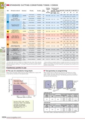
Profile MillingSlot MillingShoulderMillingFace MillingHigh FeedMilling S TA N D A R D CUTTING CONDITIONS TXN06 / EXN06 Cutting Feed per tooth speed fz (mm/t) ISO Workpiece material Hardness Priority Grades Chip-breakerVc(m/min)Tool dia: Feed when ø32, CICT = 2 ø35, CICT = 2 ø40, CICT = 3DCX (mm)plungingfzø32 ~ ø200(mm/t)nVfnVfnVf Carbon steels First choice AH3035 MJ 1,990 3,980 1,820 3,640 1,590 4,770 S45C, S55C etc. ~ 300HB 100 - 300 0.5 - 1.5 0.15 C45, C55, etc. Wear resistance AH8015 MJ Vc = 200 m/min, fz = 1.0 mm/t Alloy steels First choice AH3035 MJ 1,990 3,980 1,820 3,640 1,590 4,770 SCM440, SCr415 etc. ~ 300HB 100 - 300 0.5 - 1.5 0.15 42CrMo4, 17Cr3, etc. Wear resistance AH8015 MJ Vc = 200 m/min, fz = 1.0 mm/t 30 ~40HRC First choice 1,490 2,380 1,360 2,180 1,190 2,860AH3035ML100 - 2000.5 - 1.00.15Vc = 150 m/min, fz = 0.8 mm/t Prehardened steelsNAK80, PX5, etc.30 ~40HRCFracture resistance AH3035 MJ 100 - 200 0.5 - 1.5 1,490 2,980 1,360 2,720 1,190 3,5700.15Vc = 150 m/min, fz = 1.0 mm/t 30 ~40HRC Wear resistance 1,490 2,380 1,360 2,180 1,190 2,860AH8015ML100 - 2000.5 - 1.00.15Vc = 150 m/min, fz = 0.8 mm/t Stainless steelsSUS304, SUS316, etc.X5CrNi18-10, etc.X5CrNiMo17-12-2, etc.First choiceAH3035ML~ 200HB100 - 1500.3 - 0.8Fracture resistanceAH3035MJ1,1901,4301,0901,310950 1,7100.1Vc = 120 m/min, fz = 0.6 mm/t Gray cast irons 150 ~250HB First choice AH120 MJ 1,990 3,980 1,820 3,640 1,590 4,770100 - 3000.5 - 1.50.15Wear resistanceAH8015MJVc = 200 m/min, fz = 1.0 mm/t FC250, FC300, etc. GG25, GGG30, etc. 150 ~250HB First choice AH120 MJ 1,490 2,980 1,360 2,720 1,190 3,57080 - 2000.5 - 1.50.15Wear resistanceAH8015MJVc = 150 m/min, fz = 1.0 mm/t Titanium alloy Ti-6AI-4V, etc. First choice AH130 ML 400 400 360 360 320 480~ 40HRC30 - 600.3 - 0.70.08Fracture resistanceAH130MJVc = 40 m/min, fz = 0.5 mm/t Approach Heat-resistance alloyInconel, Hasteroy, etc.First choice~ 40HRCFracture resistanceAH725AH725MLMJ 300 120 270 110 240 14020 - 500.1 - 0.30.05Vc = 30 m/min, fz = 0.2 mm/t angle10°-20° Hot mold steelSKD61, etc.X40CrMoV5-1, etc.40 ~55HRCFirst choiceAH8015 MH 1,190 710 1,090 650 950 85080 - 1500.1 - 0.50.05Low resistanceAH8015MJVc = 120 m/min, fz = 0.3mm/t 45° Hot mold steel of D.T.CmaterialsDAC**, DH**, DIEVER, etc40 ~55HRCFirst choiceFracture resistanceAH8015MJAH8015MH 800 320 730 290 640 38050-1000.1 - 0.30.05Vc = 80 m/min, fz = 0.2mm/t Cold mold steel 55 ~65HRC 600 120 550 110 480 140First choiceAH8005MH50 - 700.05 - 0.20.03Vc = 60 m/min, fz = 0.1 mm/t 70° SKD11, etc.X153CrMoV12, etc.55 ~65HRC Fracture resistance AH8015 MH 600 60 550 55 480 7050 - 700.03 - 0.10.03Vc = 60 m/min, fz = 0.05 mm/t 85° ∙ The above table shows the conditions for standard shank type cutters. When using longshank type cutters, the number of teeth may be different. In this case, the cutting conditions∙ Cutting conditions are generally limited by the rigidity and power of the machine and therigidity of the workpiece. When setting the conditions, start from half of the values of the should be changed by referring to: “The usage of standard and long shanks” shown in standard cutting conditions and then increase the value gradually while making sure the previous page. machine is running normally. 88° Cautionary points in use 90° The use of a standard or long shank Tool geometry on programming When using a long shank, please lower the cutting conditions (Vc, fz, ap) to 70% When programming for CAM, the tool should be considered as a radius of the maximum conditions for the standard shank. cutter. Usually, the corner radius should be set as R = 3.0 mm. If a larger Others radius is used, overcutting will occur. The following table shows the amount left uncut (t1) and overcut (t2). 1.5 Standard shank Amount left overcut Vc = 100 ~ 300 m/min t2 1.0 RE 15° 0.5 Long shankVc = 80 ~ 200 m/min LE t1Amount leftuncutRPG t1 RPGCorner R whenprogramming LNMU06-MJ/ML 0 0.5 1.0 1.5 2.0Feed per tooth: fz (mm/t)Max. depth ofcutCorner radiusAPMX(mm)RE LE (mm) Corner R when Amount leftprogramming:uncutRPGt1 (mm)Amount leftovercutt2 (mm) 2.0 1.0 - 1.5 2.0 6.0 3.0 0.77 - 4.0 0.54 0.26 Tool dia.: DCX = ø32 ~ 40 mm Workpiece: S55C / C55 (200HB) LNGU06-MH L/D ratio of overhangStandard shank: L/D ) 3Long shank: L/D = 4 Max. depth ofcutCorner radiusAPMX(mm)RE LE (mm) Corner R when Amount leftprogramming:uncutRPGt1 (mm)Amount leftovercutt2 (mm) 2.0 0.9 - 1.5 2.0 6.0 3.0 0.66 - 4.0 0.41 0.26 Each value in table is calculated theoretically at the maximum condition. H034 www.tungaloy.com Depth of cut: ap (mm) APMX Max. depth of cut