Общий каталог Tungaloy 2020 - 2021 - страница 828
Навигация
 Брошюра Tungaloy новая продукция
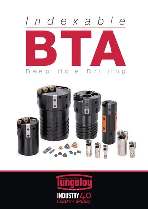 Каталог Tungaloy глубокое сверление 1
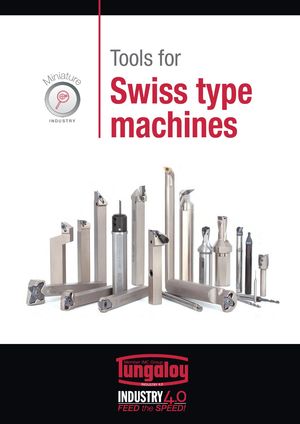 Каталог Tungaloy инструмент для автоматов швейцарского типа
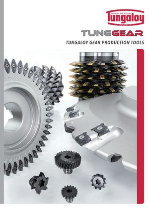 Каталог Tungaloy зубофрезерование
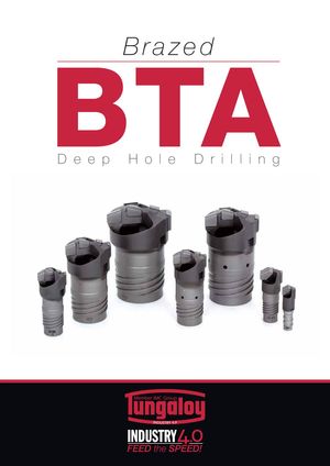 Каталог Tungaloy глубокое сверление 2
- A Grade
- Grade contents
- CVD - Coated Grade
- PVD - Coated Grade
- Ceramic
- Cermet
- CBN
- PCD (T-DIA)
- Uncoated Cemented Carbide
- Grade - Comparison Chart
- CVD Coated Grades for Turning
- PVD Coated Grade for Turning
- Cermet for Turning
- Cemented Carbide for Turning
- PCBN and PCD for Turning
- Ceramics for Turning
- CVD Coated Grade for Milling
- PVD Coated Grade for Milling
- Cermet for Milling
- Cemented Carbide for Milling
- PCBN and PCD for Milling
- Ceramics for Milling
- Chipbreaker Comparison Chart
- Negative insert type
- Positive insert type
- B Insert
- Insert - Content structure
- Insert Contents
- General insert for Turning
- Designation system for Insert
- Chipbreaker Guide
- Negative - Steel
- Negative - Stainless Steel
- Negative - Cast Iron
- Negative - Non-ferrous Metal
- Negative - Superalloys and titanium
- Negative - Hard Materials
- Positive - Steel
- Positive - Stainless Steel
- Positive - Cast Iron
- Positive - Non-ferrous Metal
- Positive- Superalloys and titanium
- Positive - Hard Materials
- Chipbreaker Overview
- Negative type with hole
- Negative type without hole
- Positive 7° with hole
- Positive 11° with hole
- Positive 7° with hole
- Positive 5° with hole
- Positive 11° without hole
- Double-sided positive type with hole
- Positive 7° without hole
- Negative
- CN
- DN
- RN
- SN
- TN
- VN
- WN
- YN
- KN
- HN
- Positive
- CC
- CP
- DC
- DP
- DX
- EP
- RC
- RT
- SC
- SP
- TC
- TP
- VB
- VC
- VP
- WP
- VX
- WB
- WX
- YW
- JXF
- JXR
- JXB
- JTB
- J10E
- 10E
- CBN
- Features
- BXA20
- WavyJoint
- GNGA type CBN
- HP Chipbreaker
- Designation System for T-CBN (PCBN) Inserts
- Negative type
- Positive type
- PCD
- Negative type
- Positive type
- Technical Guide
- T-CBN series for hardened steel and hard material
- T-CBN series for sintered metal
- T-CBN series for grey cast iron and ductile cast iron
- T-CBN Series - Honing specifications
- Features - PCD grade, T-DIA series
- C External Toolholder
- External Toolholder - Content structure
- Main products
- Designation system for Toolholders
- Quick Guide
- Negative type
- Positive type
- Features
- TurnTen-Feed
- ISO-EcoTurn
- Cutting edge
- L
- J
- N
- V
- P
- A
- G
- B
- R
- X
- D
- S
- K
- F
- Q
- H
- Special
- Technical Guide
- Parts for coolant hose
- FixRTurn - Standard cutting conditions
- MiniForce-Turn - Standard cutting conditions
- TurnTen-Feed - Standard cutting conditions
- TurnFeed - Standard cutting conditions
- TurnTec - Standard cutting conditions
- DimpleFX - Standard cutting conditions
- D Internal Toolholder
- Internal Toolholder - Content structure
- Main products
- Designation system for Toolholders
- Quick Guide
- Positive type
- Negative type
- Features
- BoreMeister
- StreamJetBar
- Cutting edge
- L
- X
- J
- K
- F
- U
- Q
- Z
- Others
- Technical Guide
- Sleeves for StreamJetBar
- MiniForce-Turn - Standard cutting conditions
- TurnTec - Standard cutting conditions
- E Threading tool
- Threading Tool - Content structure
- Main products
- Quick Guide - Applicable tool
- External threading
- Internal threading
- Features
- TetraMini-Cut
- DuoJust-Cut
- Insert for threading
- For Energy
- API Round
- API Round (For tool-rotating machines)
- API Buttress
- API Buttress (For tool-rotating machines)
- General
- 60° thread angle
- 55° thread angle (General purpose)
- ISO metric (General purpose)
- Unified (General purpose)
- For Pipe
- Whitworth, Parallel pipe thread
- BSPT (for Pipe)
- NPT (for Pipe)
- NPTF
- For Machine parts
- 30° Trapezoidal / DIN103
- Round / DIN405
- For Aerospace industry
- UNJ
- MJ
- For Machine parts, Pipe
- 29° Trapezoidal / ACME
- 29° Trapezoidal/ STUB ACME
- Toolholder for threading
- Technical Guide
- Designation system for TT-type insert
- Designation system for ST-type insert
- TungThread - Standard cutting conditions
- TungT-Clamp - Standard cutting conditions
- TetraMini-Cut - Standard cutting conditions
- DuoJust-Cut - Standard cutting conditions
- TinyMini-Turn - Standard cutting conditions
- Replacement of shim
- F Parting, Grooving
- Parting, Grooving - Content structure
- Par ting, Grooving - Machining Overview
- Quick Guide
- Features
- TungCut
- External grooving
- TungCut
- TetraMini-Cut
- TetraForce-Cut
- My-T Series
- Toolholder for 2 corner insert
- Toolholder for 1 corner insert
- 2 corner insert
- Standard cutting conditions
- Chipbreaker Guide
- 1 corner insert
- Chipbreaker Guide
- Standard cutting contions
- TungT-Clamp
- Standard cutting conditions
- Insert
- Applicable toolhoder for GTGN type insert
- GTGN type insert
- Standard cutting conditions
- TungHeavyGroove
- Chipbreaker Guide
- Insert
- Standard cutting conditions
- Others
- Internal grooving
- TungCut
- Insert
- Chipbreaker Guide
- Standard cutting conditions
- My-T Series
- Insert
- Chipbreaker Guide
- Standard cutting conditions
- TungT-Clamp
- Insert
- Standard cutting conditons
- Applicable toolhoder for GTGN type insert
- GTGN type insert
- Standard cutting conditions
- Others
- Face grooving
- EasyMulti-Cut
- Chipbreaker Guide
- Insert
- Standard cutting conditions
- TungCut
- Insert
- Chipbreaker Guide
- Standard cutting conditions
- My-T Series
- Insert
- Chipbreaker Guide
- Standard cutting conditions
- Others
- Grooving and parting
- TungCut
- Insert
- Chipbreaker Guide
- Standard cutting conditions
- My-T Series
- Toolholder for 2 corner insert
- Insert
- Standard cutting conditions
- Chipbreaker Guide
- Toolhoder for 1 corner insert
- Insert
- Chipbreaker Guide
- Standard cutting conditions
- Undercutting, profiling
- TungCut
- Insert
- Standard cutting conditions
- Chipbreaker Guide
- Technical guide
- Parts for coolant hose
- G Miniature Machining
- Miniature Machining - Content structure
- Main products
- Quick Guide
- Miniature External Turning
- Miniature Internal Turning
- Miniature Grooving
- Miniature Parting
- Miniature Threading
- Miniature Internal Turning - TinyMini-Turn
- Features
- TungTurn-Jet
- DirectTung-Jet system
- MiniForce-Turn
- External turning
- L
- J, U
- N
- P
- A
- G
- D
- F
- X
- Others
- Technical Guide
- MiniForce-Turn - Standard cutting conditions
- J-Seires - Standard cutting conditions
- TinyMini-Turn
- Internal turning
- Internal thrading
- Internal grooving
- Face grooving
- Standard cutting conditions
- Grooving
- TetraMini-Cut
- Insert
- Standard cutting conditions
- TetraForce-Cut
- Insert
- Standard cutting coditions
- J-Series
- Applicable toolholder for JTG insert
- Insert - JTG
- Standard cutting conditions
- Applicatble toolholder for JXG insert
- Insert - JXG
- Applicable toolholder for JVG insert
- Insert - JVG
- JXG, JVG - Standard cutting conditions
- TungHeavyGroove
- Insert
- Standard cutting conditions
- Threading
- TungThread
- J-Series
- Insert - JXT
- Insert - JTT
- Standard cutting conditions
- Parting
- DuoJust-Cut
- Insert
- Standard cutting conditions
- TungCut
- Chipbreaker Guide
- Insert
- Standard cutting conditions
- H Milling Cutter
- Milling Cutter - Content structure
- Designation system
- Designation system for Inser t
- Application Overview
- Quick Guide
- High-Feed Milling
- Face Milling
- Shoulder milling
- Slot milling
- Profile milling
- Thread milling
- High FeedMilling
- Features
- DoFeed
- TungForce-Feed
- TungForce-Feed
- Insert
- Standard cutting conditions
- DoFeed 03
- Insert
- Standard cutting conditions
- DoFeed 06
- Insert
- Standard cutting conditions
- DoTwistBall
- Insert
- Standard cutting conditions
- DoFeedQuad
- Insert
- Standard cutting conditions
- MillQuadFeed
- Insert
- Standard cutiing conditions
- MillFeed
- Insert
- Standard cutting conditions
- Face Milling
- Features
- TungSpeed-Mill
- DoTriple-Mill
- Insert
- Standard cittiong conditions
- DoOcto
- Insert
- Standard cittiong conditions
- DoQuad-Mill
- Insert
- Standard cittiong conditions
- DoPent
- Insert
- Standard cittiong conditions
- TungMill - TAW/EAW
- Insert
- Standard cittiong conditions
- TungSpeed-Mill - TPYP/EPYP
- Insert
- Standard cittiong conditions
- TungSpeed-Mill - TPYD/EPYD
- Insert
- Standard cittiong conditions
- TungMill - TFE/EFE
- Insert
- Standard cittiong conditions
- TungMill - DPD/EDPD
- Insert
- Standard cutting conditions
- Other tools
- S-TAQ system
- QC system for TAC Mills
- Shoulder milling
- Features
- DoForce-Tri
- Tung-Tri
- DoForce-Tri
- Insert
- Standard cutting conditions
- Tung-Tri
- Insert
- Standard cutting conditions
- TungTri-Shred
- Insert
- Standard cutting conditions
- TungForce-Rec
- Insert
- Standard cutting conditions
- TungRec 07
- Insert
- Standard cutting conditions
- TungRec 11
- Insert
- Standard cutting conditions
- TungRec 18
- Insert
- Standard cutting conditions
- TungQuad
- Insert
- Standard cutting conditions
- TungMill - TPW-EPW
- Insert
- Standard cutting conditions
- DoRec
- Insert
- Standard cutting conditions
- TecMill
- Insert
- Standard cutting conditions
- TungAlu-Mill
- Insert
- Standard cutting conditions
- Other tools
- Slot Milling
- Features
- TungUniversalSlot
- Insert
- Standard cutting conditions
- TungThinSlit
- Insert
- Standard cutting conditions
- TungUniversalSlot
- Insert
- Standard cutting conditions
- TecTangentialSlot
- Insert
- Standard cutting conditions
- Profile Milling
- Features
- ProfileMill series
- BallFinishNose
- BallRoughNose
- Insert
- Standard cutting conditions
- BallFinishNose
- Insert
- Standard cutting conditions
- DoMini-Mill
- Insert
- Standard cutting conditions
- FixRMill
- Insert
- Standard cutting conditions
- RoundSplit
- Insert
- Standard cutting conditions
- Other tools
- I Endmill
- EndMill - Content structure
- Main products
- Solid Endmill
- Quick Guide
- Designation system
- Features
- Square
- VariableMeister
- Standard cuting conditions
- FinishMeistrer / ShredMeister
- Standard cutting conditions
- SolidMeister
- Standard cutting conditions
- Continuation of SolidMeister
- Standard cutting conditions
- High feed
- FeedMiester
- Standard cutting conditions
- Ball
- Standard cutting conditions
- Exchangeable Endmill
- TungMeister
- Quick Guide
- Features
- Designation system
- Square
- Standard cutting conditions
- Radius
- VRB, VRC, VRD
- Standard cutting conditions
- VFX
- Standard cutting conditions
- Ball
- Standard cutting conditions
- Spot drilling
- Standard cutting conditions
- Counterboring
- Standard cutting conditions
- Chamfering
- Staandard cutting conditions
- Slotting
- Standard cutting conditions
- Shank
- Other tools
- Threading endmill
- Features
- Solid carbide endmill - SolidThread
- Designation System
- ISO metric
- Unified
- Whitworth
- BSPT
- NPT
- NPTF
- MJ
- UNJ
- Standard cutting conditions
- TungMeister
- Designation System
- ISO metric
- Unified
- Whitwor th
- 60° par tial profile
- 55° par tial profile
- Standard cutting conditions
- ETTL
- Standard cutting conditions
- Other tools
- Milling insert
- J Drilling Tool
- Drilling Tool - Content structure
- Main product
- Basic Selection of Drilling Tools
- Quick Guide
- General drilling
- Deep drilling
- 2 Effective Drill
- DrillMeister
- Features
- TID L/D=1.5
- TID L/D=3
- TID L/D=5
- TID L/D=8
- TID L/D=12
- TIDC L/D=3
- TIDC L/D=5
- Chamfering adapter
- Drill head
- DMP General purpose
- DMC High precision machining
- Standard cutting conditions
- DrillForce-Meister
- Drill head
- Standard cutting coditions
- Regrinding holder
- SolidDrill
- Quick Guide
- DSW
- DSW-DE3 L/D=3
- DSW-DE5 L/D=5
- DSW-DI5 L/D=5
- DSW-DI8 L/D=8
- Designation system
- Standard cutting coditions
- DSX
- DSX-F03 L/D=3
- DSX-F05 L/D=5
- DSX-F08 L/D=8
- Standard cutting conditions
- DSE
- DSE-F02 L/D=2
- DSE-F03 L/D=3
- Standard cutting conditions
- DSM
- Standard cutting conditions
- DSM-CP
- Standard cutting conditions
- FDC-S
- L/D=5
- L/D=8
- Standard cutting conditions
- CDS
- Standard cutting cnditions
- Indexable drill
- TungSix-Drill
- Features
- L/D=2
- L/D=3
- L/D=4
- Standard cutting conditions
- Insert
- Chamfering tool
- TungDrillTwisted
- L/D=2
- L/D=3
- L/D=4
- L/D=5
- Insert
- Standard cutting conditions
- Chamfering tool
- EZ sleeve
- TundDrillBig
- TDB, TDS cartridge set
- Insert
- Standard cutting conditions
- TDB, TDX cartridge set
- Insert
- Standard cutting conditions
- TDP
- Insert
- Standard cutting conditions
- Drilling Insert
- Deep Hole Drill
- Indexable Gundrill guide
- DeepTri-Drill
- Features
- MCTR L/D=10
- MCTR L/D=15
- MCTR L/D=20
- MCTR L/D=25
- MCTRCH L/D=25
- MCTR L/D=8
- MCTR L/D=10
- MCTR L/D=15
- MCTR L/D=25
- TRLG
- TRLGCH
- TRLG-F
- Insert
- Guide pad
- Standard cutting conditions
- SLJ
- Standard cutting conditions
- BTA tool
- Drill Head Category
- Drill Tube Category
- Tri-Fine
- Insert
- Guide pad
- Fine-Beam
- Insert
- Guide pad
- Unidex
- Insert
- Standard cutting conditions
- Brazed drill head
- Standard cutting conditions
- Drill tube
- HF drill
- K Tooling System
- Tooling System - Content structure
- Main products
- TungCap
- Features
- TungCap tooling system
- External turning
- L
- J
- N
- V
- Internal turning
- L
- U
- X
- Q
- Treading
- Grooving
- Drilling
- Milling
- Adapter
- Side-lock holder
- SwissBore
- Features
- Boring head / Boring bar
- Digital display unit
- Clamping units
- Nomenclature for clamping units
- Clamping units & tools for CNC lathes
- Clamping torque
- TungHold
- DIN69871
- DIN 69893 HSK
- BT MAS 403
- DIN2080
- Other holders
- TungFit adapter
- ER Collet Chucking System
- ER collet
- TungShrink, ER collet type
- TungShrink - Induction heating unit for shrink tool chucking
- TungShrink - Quick change type
- Tapping attachment for ER collet chuck holders
- Pull stud with JIN/ANSI retention knob (BT), for MAZAK machines
- Parts
- Easy Lock - Electrical nut-clamp torque control device
- SpinJet
- Wireless RPM speed display
- Collet
- BeamWrench
- SwissBore
- Wide range of variation quick change system
- Digital display unit
- Boring head / boring bar
- Adapter
- PINZBOHR®
- Features
- System
- Designation System
- Boring head
- Arbor
- Adapter
- Parts
- Cartridge
- List of ISO Standard Cartridges by Application
- A-type (Positive rake, compact type)
- Top-Borer Tool
- Boring bar tool
- L User’s Guide
- User´s guide - contents
- Parts for Tools
- Screws
- Shims
- Clamps
- Clamp Sets
- Levers
- Pins
- Chipbreaker Pieces
- Springs (Springs for Shims)
- Coolant Supply Attachment
- Sizing Plates
- Washers
- Locators
- Insert locking wedges
- Locator adjusting wedges
- Fine adjusting screws
- Cover
- Technical Reference
- Turning Tools
- Grooving and Parting Tools
- Threading Tools
- Thread Milling CNC Program for Internal Thread
- Milling Tools
- Endmills
- Drilling Tools
- Symbols of Metals
- Approximate Conversion Table of Hardness
- Surface Roughness
- GC_2020-2021_G_M_Index
- Numeric
- A
- B
- C
- D
- E
- F
- G
- H
- I
- J
- K
- L
- M
- N
- O
- P
- Q
- R
- S
- T
- U
- V
- W
- X
- Y
- Z
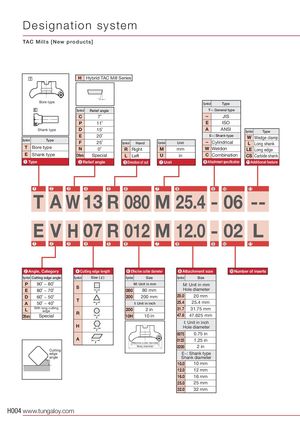
Designation syste m
TAC Mills [ N e w p ro d u c t s ]
H Hybrid TAC Mill Series T
Bore type Symbol Type
| E | Symbol | Relief angle | T~: General type | ||||
| C | 7˚ | - | JIS | ||||
| P | 11˚ | E | ISO | ||||
| Shank type | D | 15˚ | A | ANSI | |||
| Symbol | Type | ||||||
| E | 20˚ | E~: Shank type | W | Wedge clamp | |||
| Symbol | Type F | 25˚ | - | Cylindrical | Long shank |
Symbol Hand Symbol Unit L
T Bore type Right Weldon
N 0˚ R M mm W LE Long edge
E Shank type Special Left C Combination Carbide shank
| Others | L | U | in | CS | |||||
| 1 Type | 3 Relief angle | 5 Direction of cut | 7 Unit | 9 Attachment specification | 11 Additional feature | ||||
| 1T A2 | 3 | 134 | 5 | 6 | 7 | 8 | 9 | 10 | 11 |
| W | R 080 M 25.4 - 06 -- | ||||||||
| E V H 07 R 012 M 12.0 - 02 L | |||||||||
| 1 | 2 3 | 4 | 5 | 6 | 7 | 8 | 9 | 10 | 11 |
| 2 Angle, Category | 4 Cutting edge length | 6 Effective cutter diameter | 8 Attachment size | 10 Number of inserts | |||
| Symbol Cutting edge angle | Symbol | Size (R) Symbol | Size | Symbol | Size | ||
| P | 90˚ ~ 80˚ | M: Unit in mm | M: Unit in mm | ||||
| S | Hole diameter | ||||||
| E | 80˚ ~ 70˚ | 080 | 80 mm | ||||
| R | |||||||
| D | 60˚ ~ 50˚ | 200 | 200 mm | 20.0 | 20 mm | ||
| T | |||||||
| A | 50˚ ~ 40˚ | I: Unit in inch | 25.4 | 25.4 mm | |||
| R | |||||||
| With long cutting | 31.7 | 31.75 mm | |||||
| L | edge | 200 | 2 in | ||||
| Special | R | ||||||
| Others | 10H | 10 in | 47.6 | 47.625 mm |
R I: Unit in inch H Hole diameter R
0075 0.75 in
| A 0125 | 1.25 in | |
| Effective cutter diameter R | ||
| Body diameter 0200 | 2 in | |
| Cutting | ||
| edge | E~: Shank type | |
| angle | Shank diameter | |
| 10.0 | 10 mm | |
| 12.0 | 12 mm | |
| 16.0 | 16 mm | |
| 25.0 | 25 mm | |
| 32.0 | 32 mm |