Каталог Sumitomo сверла и развертки - страница 88
Навигация
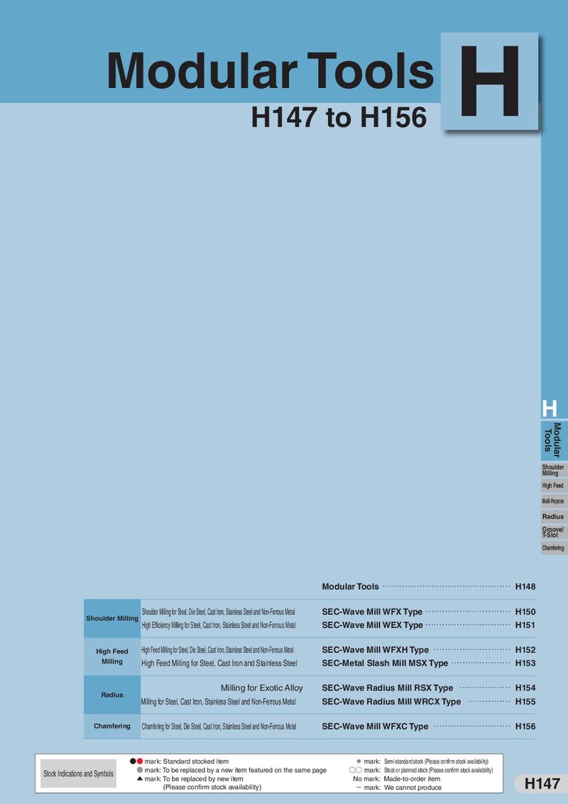 Каталог Sumitomo модульные фрезерные системы
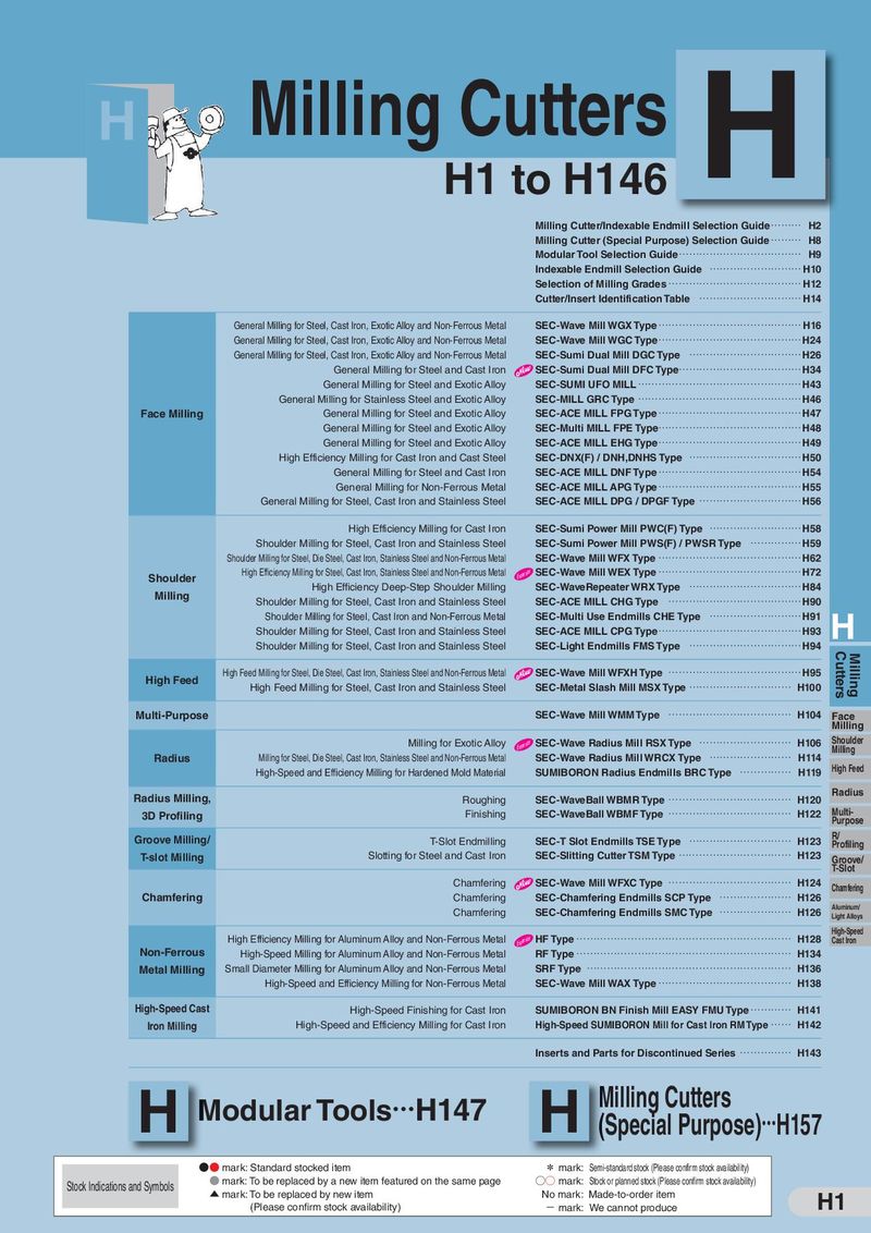 Каталог Sumitomo фрезы со сменными пластинами
 Каталог Sumitomo запасные части
 Каталог Sumitomo пластины с режущей кромкой-моноалмаз Sumicristal
 Каталог Sumitomo микроинструмент
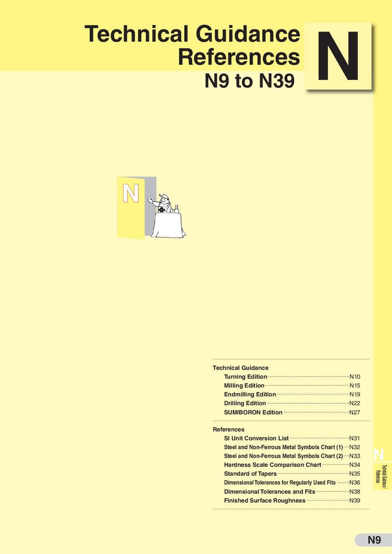 Техническая информация Sumitomo
- J001
- J1-001
- J1-002
- J1-003
- J1-004
- J1-005
- J1-006
- J1-007
- J1-008
- J1-009
- J1-010
- J1-011
- J1-012
- J1-013
- J1-014
- J1-015
- J1-016
- J1-017
- J1-018
- J1-019
- J1-020
- J1-021
- J1-022
- J002
- J003
- J004
- J005
- J006
- J007
- J008
- J009
- J010
- J011
- J012
- J013
- J014
- J015
- J016
- J017
- J018
- J019
- J020
- J021
- J022
- J023
- J024
- J025
- J026
- J027
- J028
- J029
- J030
- J031
- J032
- J033
- J034
- J035
- J036
- J037
- J038
- J039
- J040
- J041
- J042
- J043
- J044
- J045
- J046
- J047
- J048
- J049
- J050
- J051
- J052
- J053
- J054
- J055
- J056
- J057
- J058
- J059
- J060
- J061
- J062
- J063
- J064
- J065
- J066
- J067
- J068
- J069
- J070
- J071
- J072
- J073
- J074
- J075
- J076
- J077
- J078
- J079
- J080
- J081
- J082
- J083
- J084
- J085
- J086
- J087
- J088
- J089
- J090
- J091
- J092
- J093
- J094
- J095
- J096
- J097
- J098
- J099
- J100
- J101
- J102
- J103
- J104
- J105
- J106
- J107
- J108
- J109
- J110
- J111
- J112
- J113
- J114
- J115
- J116
- J117
- J118
- J119
- J120
- J121
- J122
- J123
- J124
- J125
- J126
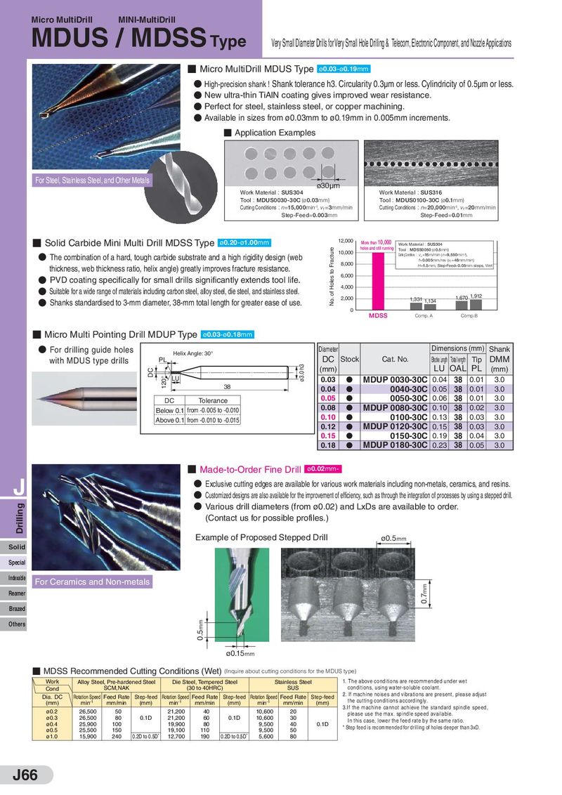
Micro MultiDrill MINI-MultiDrill
MDUS / MDSS
Type Very Small Diameter Drills for Very Small Hole Drilling & Telecom, Electronic Component, and Nozzle Applications
- Micro MultiDrill MDUS Type
ø0.03-ø0.19mm
- High-precision shank ! Shank tolerance h3. Circularity 0.3μm or less. Cylindricity of 0.5μm or less.
- New ultra-thin TiAlN coating gives improved wear resistance.
- Perfect for steel, stainless steel, or copper machining.
- Available in sizes from ø0.03mm to ø0.19mm in 0.005mm increments.
- Application Examples
For Steel, Stainless Steel, and Other Metals
ø30μm
Work Material : SUS304 Work Material : SUS316 Tool : MDUS0030-30C (ø0.03mm) Tool : MDUS0100-30C (ø0.1mm) Cutting Conditions : n=15,000min -1, v =3mm/min Cutting Conditions : n=20,000min -1, v =20mm/min f f Step-Feed=0.003mm Step-Feed=0.01mm
- Solid Carbide Mini Multi Drill MDSS Type 12,000
| ø0.20-ø1.00mm | More than 10,000 | : | |
| Work Material | SUS304 | ||
| holes and still running | Tool : MDSS0050 (ø 0.5mm) |
10,000 :
The combination of a hard, tough carbide substrate and a high rigidity design (web Cutting Conditions vc =15m/min ( n=9,550 min-1),
f=0.005mm/rev (vf =48 mm/min) 8,000 H=1.5mm, Step-Feed=0.05mm steps, Wet thickness, web thickness ratio, helix angle) greatly improves fracture resistance.
- 6,000
PVD coating specifically for small drills significantly extends tool life.
- Suitable for a wide range of materials including carbon steel, alloy steel, die steel, and stainless steel. 4,000
1,670 1,912
| ● | 2,000 | 1,331 | |||
| Shanks standardised to 3-mm diameter, 38-mm total length for greater ease of use. | 1,134 | ||||
| 0 |
MDSS Comp. A Comp.B
- Micro Multi Pointing Drill MDUP Type
ø0.03-ø0.18mm
| ●For drilling guide holes | Helix Angle: 30° | Diameter | Dimen | sion | s(mm) | Shank | |
| with MDUS type drills | .0 h3 C PL | DC (mm) | Stock Cat. No. | Effective Length LU To | tal leng OA | th L Tip PL | DMM (mm) |
| 20° ø3 D LU | 0.03 | D MDUP 0030-30C | 0.04 | 38 | 0.01 | 3.0 | |
| 1 38 | 0.04 | D 0040-30C | 0.05 | 38 | 0.01 | 3.0 | |
| DC Tolerance | 0.05 | D 0050-30C | 0.06 | 38 | 0.01 | 3.0 | |
| Below 0.1 from -0.005 to -0.010 | 0.08 | D MDUP 0080-30C | 0.10 | 38 | 0.02 | 3.0 | |
| Above 0.1 from -0.010 to -0.015 | 0.10 | D 0100-30C | 0.13 | 38 | 0.03 | 3.0 | |
| 0.12 | D MDUP 0120-30C | 0.15 | 38 | 0.03 | 3.0 | ||
| 0.15 | D 0150-30C | 0.19 | 38 | 0.04 | 3.0 | ||
| 0.18 | D MDUP 0180-30C | 0.23 | 38 | 0.05 | 3.0 |
J
Solid Special Indexable For Ceramics and Non-metals Reamer Brazed
- Made-to-Order Fine Drill
ø0.02mm-
- Exclusive cutting edges are available for various work materials including non-metals, ceramics, and resins.
- Customized designs are also available for the improvement of efficiency, such as through the integration of processes by using a stepped drill.
- Various drill diameters (from ø0.02) and LxDs are available to order. (Contact us for possible profiles.) Example of Proposed Stepped Drill ø0.5
mm
| MDSS | Recomm | ended | Cutting | Conditio | ns (Wet 0.5mm | )(Inquire a ø0.15m | bout cutting m | conditions | for the MD |
| Work Cond | Alloy Stee | l, Pre-harde SCM,NAK | ned Steel | Die Ste (3 | el, Tempere 0 to 40HRC | d Steel ) | S | tainless Ste SUS | el |
| Dia. DC (mm) | Rotation Speed min-1 | Feed Rate mm/min | Step-feed (mm) | Rotation Speed min-1 | Feed Rate mm/min | Step-feed (mm) | Rotation Speed min-1 | Feed Rate mm/min | Step-feed (mm) |
| ø0.2 | 26,500 | 50 | 21,200 | 40 | 10,600 | 20 | |||
| ø0.3 | 26,500 | 80 | 0.1D | 21,200 | 60 | 0.1D | 10,600 | 30 | |
| ø0.4 | 25,900 | 100 | 19,900 | 80 | 9,500 | 40 | 0.1D | ||
| ø0.5 | 25,500 | 150 | 19,100 | 110 | 9,500 | 50 | |||
| ø1.0 | 15,900 | 240 | 0.2D to 0.5D | 12,700 | 190 | 0.2D to 0.5D | 5,600 | 80 |
Others
3.If the machine cannot achieve the standard spindle speed,