Каталог Sumitomo сверла и развертки - страница 116
Навигация
 Каталог Sumitomo модульные фрезерные системы
 Каталог Sumitomo фрезы со сменными пластинами
 Каталог Sumitomo запасные части
 Каталог Sumitomo пластины с режущей кромкой-моноалмаз Sumicristal
 Каталог Sumitomo микроинструмент
 Техническая информация Sumitomo
- J001
- J1-001
- J1-002
- J1-003
- J1-004
- J1-005
- J1-006
- J1-007
- J1-008
- J1-009
- J1-010
- J1-011
- J1-012
- J1-013
- J1-014
- J1-015
- J1-016
- J1-017
- J1-018
- J1-019
- J1-020
- J1-021
- J1-022
- J002
- J003
- J004
- J005
- J006
- J007
- J008
- J009
- J010
- J011
- J012
- J013
- J014
- J015
- J016
- J017
- J018
- J019
- J020
- J021
- J022
- J023
- J024
- J025
- J026
- J027
- J028
- J029
- J030
- J031
- J032
- J033
- J034
- J035
- J036
- J037
- J038
- J039
- J040
- J041
- J042
- J043
- J044
- J045
- J046
- J047
- J048
- J049
- J050
- J051
- J052
- J053
- J054
- J055
- J056
- J057
- J058
- J059
- J060
- J061
- J062
- J063
- J064
- J065
- J066
- J067
- J068
- J069
- J070
- J071
- J072
- J073
- J074
- J075
- J076
- J077
- J078
- J079
- J080
- J081
- J082
- J083
- J084
- J085
- J086
- J087
- J088
- J089
- J090
- J091
- J092
- J093
- J094
- J095
- J096
- J097
- J098
- J099
- J100
- J101
- J102
- J103
- J104
- J105
- J106
- J107
- J108
- J109
- J110
- J111
- J112
- J113
- J114
- J115
- J116
- J117
- J118
- J119
- J120
- J121
- J122
- J123
- J124
- J125
- J126
SumiDrill
WDX Type
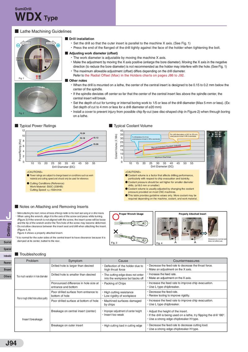
■ Lathe Machining Guidelines
■ Drill installation
Internal bore smaller Internal bore larger ・Set the drill so that the outer insert is parallel to the machine X axis. (See Fig. 1)
・Press the end of the flanged of the drill tightly against the face of the holder when tightening the bolt.
■ Adjusting work diameter (offset)
Central ・The work diameter is adjustable by moving the machine X axis.
Insert
Machine
X axis Peripheral
Insert
・Make the adjustment by moving the X axis positive (enlarge the bore diameter). Moving the X axis in the negative
direction (to reduce the bore diameter) is not recommended as the holder may interfere with the hole. (See Fig. 1)
・The maximum allowable adjustment (offset) differs depending on the drill diameter.
Refer to the Radial Offset (Max) in the Holders charts on pages J86 to J92.
Fig. 1 ■ Other notes
・When the drill is mounted on a lathe, the center of the central insert is designed to be 0.15 to 0.2 mm below the
center of the spindle.
・If the spindle deviates off center so far that the center of the central insert lies above the spindle center, the
central insert will break.
・Set the depth of cut for turning or internal boring work to 1/5 or less of the drill diameter (Max 5 mm or less). (Ex:
Set depth of cut to 4 mm or less for a drill diameter of ø20 mm)
Fig. 2 ・Install a cover to prevent injury from possible chip fly-out (see disc-shaped chip in Figure 2) when through boring
on a lathe.
■ Typical Power Ratings ■ Typical Coolant Volume
12 40
f 0.24 Coolant Volume ( ℓ /Min) 35 For drill diameters ø18.5 to 55 mm,
10 f 0.12 For drill diameters ø13 to 18 mm, coolant pressures of at least 1.0 MPa is recommended.
PowerRating (Kw) f 0.18 30 coolant pressures of at least 2.0 MPa is recommended.
8 25
6 f 0.06 20 Coolant Volume
15 Recommended
4
2 10
5 Minimum Discharge
0 10 15 20 25 30 35 40 45 50 55 0 10 15 20 25 30 35 40 45 50 55
Drill Diameter (DC) Drill Diameter (DC)