Оптимальный выбор Kennametal 2025 - 2026 - страница 306
Навигация
 Каталог Kennametal инновации 2019.1
 Инновационные токарные пластины с покрытиями KENGold CVD и PVD Kennametal 2025
 Новинки Kennametal - осень 2025
 Новинки Kennametal - осень 2024
 Каталог Kennametal инструментальные системы 2018
 Сверла со сменными пластинами линейки Drill Fix PRO Kennametal 2024
- Main TOC
- Turning TOC
- KCP25C - KENGOLD CVD
- KCU10B - KENGOLD PVD
- KCU25B - KENGOLD PVD
- KBH10B & KBH20B
- Quick & Easy Insert Selection
- Spare Parts & Accessories Information
- Negative Insert Toolholders
- Positive Insert Toolholders
- Boring Bars - Negative Inserts
- Boring Bars - Postivie Inserts
- ISO/ANSI Insert Grade Descriptions
- Beyond Evolution - Grooving, Turning & Cut-Off
- Application Data - Recommended Starting Speeds
- Application Data - Plunge Feed Rates
- Application Data - Turn & Profile Feed Rates
- A4 Tooling & Double-Sided Inserts
- Application Data - Recommended Starting Speeds
- Application Data - Plunge Feed Rates
- Application Data - Turn & Profile Feed Rates
- Laydown Triangle Threading
- Application Data - Recommended Starting Speeds
- Turning Toolholder & Boring Bar Torque Recommendation
- Indexable Milling TOC
- Dodeka Series
- Recommended Starting Feeds
- Recommended Starting Speeds - Dry Machining
- Receommended Starting Speeds - Wet Machining
- 7745VOD Series
- Recommended Starting Feeds
- Recommended Starting Speeds - Dry Machining
- Recommended Starting Speeds - Wet Machining
- Mill 4-11
- Recommended Starting Feeds
- Recommended Starting Speeds - Dry Machining
- Recommended Starting Speeds - Wet Machining
- Mill 4-15
- Recommended Starting Feeds
- Recommended Starting Speeds - Dry Machining
- Recommended Starting Speeds - Wet Machining
- Mill 1-10
- Recommended Starting Feeds
- Recommended Starting Speeds - Dry Machining
- Recommended Starting Speeds - Wet Machining
- Application Examples
- Mill 1-14
- Application Examples
- Recommended Starting Feeds
- Recommended Starting Speeds - Dry Machining
- Recommended Starting Speeds - Wet Machining
- Mill 4-12KT
- Recommended Starting Feeds
- 7792 High-Feed Series
- Recommended Starting Feeds
- Recommended Starting Speeds - Dry Machining
- Recommended Starting Speeds - Wet Machining
- 7713VR Series
- Recommended Starting Feeds
- Recommended Starting Speeds - Dry Machining
- Recommended Starting Speeds - Wet Machining
- 7713VR Technical Information
- Solid End Milling TOC
- HARVI I TE
- Application Data
- Application Recommendations
- HARVI Series
- Application Data
- Application Recommendations
- KOR 5DS
- Application Data
- KenCut RR
- Application Data
- MaxiMet & KenCut Aluminum
- Application Data
- GOmill PRO
- Application Data
- GOmill
- Application Data
- GOmill GP
- Application Data
- Duo-Lock
- Application Data
- Holemaking TOC
- GOdrill
- Application Data
- KENNA UNIVERSAL
- Application Data
- KenTIP FS
- HPG Application Data
- GTP Application Data
- KSEM
- Application Data
- KSEM PLUS
- Application Data
- Drill Fix PRO
- Application Data
- Feed Force Requirement
- Power Recommendation
- Torque Recommendation
- Drill Fix DFR Inserts
- Application Data
- Drill Fix DFSP Inserts
- Application Data
- Drill Fix DFT Inserts
- Application Data
- Tooling Systems TOC
- Hydraulic Chucks
- Shrink Fit Toolholders
- ER Collet Chucks
- Shell Mill Adapters
- End Mill Adapters
- Screw-On Adapters
- Chip Fan
- Material Cross Reference Guide
- Metal Cutting Safety
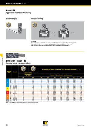
Модульное концевое фрезерование DUO-LOCK
ХАРВИ I TE
Информация применения • Торцевое погружение
Линейное торцевое погружение
Спиральное торцевое погружение
Внимание!
Для операций спирального торцевого погружения минимальный и максимальный диаметр отверстия можно рассчитать по следующей формуле: минимальный диаметр отверстия = диаметр фрезы × 1,1 + 2 × размер конфигурации угла (Re/CHF). Отношение диаметра отверстия к диаметру фрезы минимум 1:1,15. Максимальный диаметр отверстия = 2 × диаметр фрезы + 2 × размер конфигурации угла (Re/CHF). Отношение диаметра отверстия к диаметру фрезы максимум 1:1,9.
DUO-LOCK • ХАРВИ I TE
Торцевое погружение 0°–15° • Данные применения
Рекомендуемая подача на зуб (Fz = мм/зуб) для спиральной интерполяции и торцевого погружения — zeff = 2.
| Группа материалов | Максимальная глубина (мм) | Скорость резания Vc (м/мин) | Диаметр D1 (мм) для спиральной интерполяции и подача Fz | ||||||
|---|---|---|---|---|---|---|---|---|---|
| Мин | Макс | 10,0 | 12,0 | 16,0 | 20,0 | 25,0 | 32,0 | ||
| P | 1xD | 125 | 175 | 0,055 | 0,065 | 0,075 | 0,087 | 0,095 | 0,105 |
| 1xD | 125 | 175 | 0,055 | 0,065 | 0,075 | 0,087 | 0,095 | 0,105 | |
| 1xD | 125 | 175 | 0,055 | 0,065 | 0,075 | 0,087 | 0,095 | 0,105 | |
| 1xD | 110 | 150 | 0,047 | 0,054 | 0,067 | 0,078 | 0,088 | 0,095 | |
| 1xD | 75 | 140 | 0,041 | 0,048 | 0,059 | 0,068 | 0,075 | 0,080 | |
| 0,75 x D | 50 | 90 | 0,037 | 0,043 | 0,054 | 0,062 | 0,070 | 0,075 | |
| 0,75 x D | 40 | 70 | 0,031 | 0,036 | 0,044 | 0,050 | 0,055 | 0,060 | |
| M | 0,75 x D | 75 | 105 | 0,047 | 0,054 | 0,067 | 0,078 | 0,088 | 0,095 |
| 0,75 x D | 45 | 70 | 0,037 | 0,043 | 0,054 | 0,062 | 0,070 | 0,075 | |
| 0,5 x D | 40 | 65 | 0,031 | 0,036 | 0,044 | 0,050 | 0,055 | 0,060 | |
| K | 1xD | 110 | 140 | 0,055 | 0,065 | 0,075 | 0,087 | 0,095 | 0,105 |
| 1xD | 100 | 130 | 0,047 | 0,054 | 0,067 | 0,078 | 0,088 | 0,095 | |
| 0,75 x D | 90 | 120 | 0,037 | 0,043 | 0,054 | 0,062 | 0,070 | 0,075 | |
| S | 0,5 x D | 40 | 80 | 0,047 | 0,054 | 0,067 | 0,078 | 0,088 | 0,095 |
| 0,5 x D | 40 | 70 | 0,037 | 0,043 | 0,054 | 0,062 | 0,070 | 0,075 | |
| 0,3 x D | 20 | 35 | 0,024 | 0,029 | 0,036 | 0,041 | 0,047 | 0,050 | |
| 0,75 x D | 40 | 50 | 0,034 | 0,040 | 0,050 | 0,057 | 0,064 | 0,070 | |
| H | 0,75 x D | 70 | 120 | 0,041 | 0,048 | 0,059 | 0,068 | 0,075 | 0,080 |
| 0,75 x D | 60 | 110 | 0,029 | 0,034 | 0,041 | 0,048 | 0,053 | 0,056 | |
Примечание: Диаметр min и max должны быть рассчитаны по формуле спирального торцевого погружения выше.