Оптимальный выбор Kennametal 2025 - 2026 - страница 246
Навигация
 Каталог Kennametal инновации 2019.1
 Инновационные токарные пластины с покрытиями KENGold CVD и PVD Kennametal 2025
 Новинки Kennametal - осень 2025
 Новинки Kennametal - осень 2024
 Каталог Kennametal инструментальные системы 2018
 Сверла со сменными пластинами линейки Drill Fix PRO Kennametal 2024
- Main TOC
- Turning TOC
- KCP25C - KENGOLD CVD
- KCU10B - KENGOLD PVD
- KCU25B - KENGOLD PVD
- KBH10B & KBH20B
- Quick & Easy Insert Selection
- Spare Parts & Accessories Information
- Negative Insert Toolholders
- Positive Insert Toolholders
- Boring Bars - Negative Inserts
- Boring Bars - Postivie Inserts
- ISO/ANSI Insert Grade Descriptions
- Beyond Evolution - Grooving, Turning & Cut-Off
- Application Data - Recommended Starting Speeds
- Application Data - Plunge Feed Rates
- Application Data - Turn & Profile Feed Rates
- A4 Tooling & Double-Sided Inserts
- Application Data - Recommended Starting Speeds
- Application Data - Plunge Feed Rates
- Application Data - Turn & Profile Feed Rates
- Laydown Triangle Threading
- Application Data - Recommended Starting Speeds
- Turning Toolholder & Boring Bar Torque Recommendation
- Indexable Milling TOC
- Dodeka Series
- Recommended Starting Feeds
- Recommended Starting Speeds - Dry Machining
- Receommended Starting Speeds - Wet Machining
- 7745VOD Series
- Recommended Starting Feeds
- Recommended Starting Speeds - Dry Machining
- Recommended Starting Speeds - Wet Machining
- Mill 4-11
- Recommended Starting Feeds
- Recommended Starting Speeds - Dry Machining
- Recommended Starting Speeds - Wet Machining
- Mill 4-15
- Recommended Starting Feeds
- Recommended Starting Speeds - Dry Machining
- Recommended Starting Speeds - Wet Machining
- Mill 1-10
- Recommended Starting Feeds
- Recommended Starting Speeds - Dry Machining
- Recommended Starting Speeds - Wet Machining
- Application Examples
- Mill 1-14
- Application Examples
- Recommended Starting Feeds
- Recommended Starting Speeds - Dry Machining
- Recommended Starting Speeds - Wet Machining
- Mill 4-12KT
- Recommended Starting Feeds
- 7792 High-Feed Series
- Recommended Starting Feeds
- Recommended Starting Speeds - Dry Machining
- Recommended Starting Speeds - Wet Machining
- 7713VR Series
- Recommended Starting Feeds
- Recommended Starting Speeds - Dry Machining
- Recommended Starting Speeds - Wet Machining
- 7713VR Technical Information
- Solid End Milling TOC
- HARVI I TE
- Application Data
- Application Recommendations
- HARVI Series
- Application Data
- Application Recommendations
- KOR 5DS
- Application Data
- KenCut RR
- Application Data
- MaxiMet & KenCut Aluminum
- Application Data
- GOmill PRO
- Application Data
- GOmill
- Application Data
- GOmill GP
- Application Data
- Duo-Lock
- Application Data
- Holemaking TOC
- GOdrill
- Application Data
- KENNA UNIVERSAL
- Application Data
- KenTIP FS
- HPG Application Data
- GTP Application Data
- KSEM
- Application Data
- KSEM PLUS
- Application Data
- Drill Fix PRO
- Application Data
- Feed Force Requirement
- Power Recommendation
- Torque Recommendation
- Drill Fix DFR Inserts
- Application Data
- Drill Fix DFSP Inserts
- Application Data
- Drill Fix DFT Inserts
- Application Data
- Tooling Systems TOC
- Hydraulic Chucks
- Shrink Fit Toolholders
- ER Collet Chucks
- Shell Mill Adapters
- End Mill Adapters
- Screw-On Adapters
- Chip Fan
- Material Cross Reference Guide
- Metal Cutting Safety
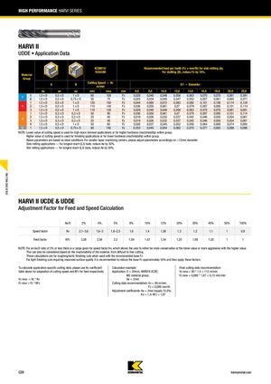
СЕРИЯ HARVI ВЫСОКОЙ ПРОИЗВОДИТЕЛЬНОСТИ
HARVI II — UDDE
Данные применения
Рекомендуемая подача на зуб (Fz = мм/зуб) для бокового фрезерования (A). Для расточки канавок (B) уменьшить Fz на 10 %.
| Группа материала | KCSM15 / KC643M | Скорость резания — Vc (м/мин) | D1 — Диаметр (мм) / Fz | |||||||||||
|---|---|---|---|---|---|---|---|---|---|---|---|---|---|---|
| Группа | ap | ae | ap | мин | макс | 6,0 | 8,0 | 10,0 | 12,0 | 14,0 | 16,0 | 18,0 | 20,0 | 25,0 |
| P | 1,5 × D | 0,5 × D | 1 × D | 60 | 100 | 0,029 | 0,040 | 0,048 | 0,056 | 0,063 | 0,070 | 0,076 | 0,081 | 0,091 |
| 1,5 × D | 0,5 × D | 0,75 × D | 50 | 75 | 0,025 | 0,034 | 0,040 | 0,047 | 0,052 | 0,057 | 0,061 | 0,065 | 0,071 | |
| K | 1,5 × D | 0,5 × D | 1 × D | 120 | 150 | 0,044 | 0,060 | 0,072 | 0,083 | 0,092 | 0,101 | 0,108 | 0,114 | 0,124 |
| 1,5 × D | 0,5 × D | 1 × D | 110 | 140 | 0,036 | 0,050 | 0,061 | 0,070 | 0,079 | 0,087 | 0,095 | 0,101 | 0,114 | |
| 1,5 × D | 0,5 × D | 1 × D | 110 | 130 | 0,029 | 0,040 | 0,048 | 0,056 | 0,063 | 0,070 | 0,076 | 0,081 | 0,091 | |
| S | 1,5 × D | 0,3 × D | 0,3 × D | 50 | 90 | 0,036 | 0,050 | 0,061 | 0,070 | 0,079 | 0,087 | 0,095 | 0,101 | 0,114 |
| 1,5 × D | 0,3 × D | 0,3 × D | 25 | 40 | 0,019 | 0,026 | 0,032 | 0,037 | 0,042 | 0,046 | 0,050 | 0,054 | 0,061 | |
| 1,5 × D | 0,3 × D | 0,3 × D | 25 | 40 | 0,019 | 0,026 | 0,032 | 0,037 | 0,042 | 0,046 | 0,050 | 0,054 | 0,061 | |
| 1,5 × D | 0,5 × D | 1 × D | 50 | 60 | 0,026 | 0,037 | 0,045 | 0,052 | 0,058 | 0,064 | 0,069 | 0,074 | 0,084 | |
| H | 1,5 × D | 0,5 × D | 0,75 × D | 80 | 140 | 0,033 | 0,045 | 0,054 | 0,062 | 0,070 | 0,077 | 0,083 | 0,088 | 0,098 |
HARVI II UCDE и UDDE — Коэффициент корректировки для расчета скорости и подачи
| Ae/D | 2% | 4% | 5% | 8% | 10% | 12% | 20% | 30% | 40% | 50% | 100% |
|---|---|---|---|---|---|---|---|---|---|---|---|
| Коэффициент скорости Kv | 2,1–3,6 | 1,6–3 | 1,6–2,5 | 1,6 | 1,4 | 1,38 | 1,3 | 1,2 | 1,1 | 1 | 0,9 |
| Коэффициент подачи KFz | 3,58 | 2,56 | 2,3 | 1,84 | 1,67 | 1,54 | 1,25 | 1,09 | 1,02 | 1 | 1 |
Примечание: Для отношения Ae/D 5% или менее указан диапазон коэффициента скорости Kv, позволяющий пользователю выбирать более консервативное значение (нижнее) или более агрессивное значение (верхнее). Это также может быть рассмотрено в зависимости от обрабатываемости материала — от трудной к легкой обработке. Эти расчеты применяются для черновых/получерновых операций при использовании рекомендуемой базовой подачи Fz. Для легких чистовых операций, требующих улучшенного качества поверхности, рекомендуется уменьшить базовую подачу Fz примерно на 50%, а затем применить эти коэффициенты.
Для расчета параметров резания, специфичных для применения, используйте коэффициент Kv из таблицы выше для адаптации скорости резания и KFz для корректировки подачи соответственно.
Формулы расчета:
Vc новая = Vc × Kv
Fz новая = Fz × KFz
Пример расчета:
Применение: D = 20 мм, HARVI II UCDE; группа материала M2; Ae = 2 мм
Рекомендация по параметрам резания: Vc = 80 м/мин; Fz = 0,089 мм/зуб
Коэффициенты корректировки: Ae = 2 мм соответствует 10,0%; Kv = 1,4; KFz = 1,67
Итоговая рекомендация по параметрам резания:
Vc новая = 80 × 1,4 = 112 м/мин
Fz новая = 0,089 × 1,67 = 0,15 мм/зуб