Общий каталог Palbit - страница 88
Навигация
 Общий каталог Palbit 2022
- General Catalogue
- Index
- NEWS
- MILLING
- Milling tool selection
- Tools Overview
- Inserts Codification
- New grade PHS
- Inserts Overview
- Face Milling
- PLUS 28088
- PLUS 90260
- PLUS 90845
- PLUS 90945
- PLUS 91245
- LINEPRO 06045
- LINEPRO 09945
- LINEPRO 00036
- Hifeed Milling
- PENTA HIFEED 06320
- HIFEED 06410
- HIFEED 06690
- HIFEED 06815
- HIFEED 50560
- HIFEED 50060
- HIFEED 06590
- Shoulder Milling
- PLUS 49090
- PLUS 17190
- PLUS 17590
- PLUS 18190
- LINEPRO 20090
- LINEPRO 20190
- LINEPRO 20290
- TGPLUS 90090
- TGPLUS 90190
- TGPLUS 90390
- ALUPRO 76090
- ALUPRO 77090
- ALUPRO 08390
- LINEPRO 06290
- LINEPRO 17090
- LINEPRO 18090
- LINEPRO 15090
- Profile Milling
- PLUS 49095
- PLUS 45095
- TOROMILL 33590|33690|33790
- TOROMILL 33890|33990
- TOROMILL X2 35190
- TOROMILL 24590|25090|25190
- TOROMILL 25290|25390
- LINEPRO 40095|40595|41095
- Hardmill
- HARDMILL 72090
- Center & Chamfer
- Spot face
- End Mills Carbide
- Straight Flutes PCD
- Solide Carbide End Mills
- Selection Guide for Solid Carbide
- HF30G S/XL
- HB30G S/L
- HB30G L
- HF 45G S
- HC45FL
- HF30HL
- HB30HL
- HC35ML
- HC38AS
- Technical Data
- Troubleshooting
- Spare Parts
- Procedures for clamping screws
- Technical Data
- Milling Grades
- Comparative Grades Chart
- Formulas & calculations
- Troubleshooting
- DRILLING
- Drills Code Key
- Nomenclature
- Overview
- Jet Drills
- Integrex Drills
- Vortex Drills
- Trepanning Drills
- Solid Carbide Drills
- ISO Driling inserts code key
- Inserts
- Spare Parts
- Technical Data
- TURNING
- New turning grades
- ISO Turning Code key
- Negative Inserts Overview
- Positive Inserts Overview
- Negative Inserts
- CN Inserts
- CNMA
- CNMG-SF
- CNMG-LC
- CNMG-MS
- CNMG-MR
- CNMG-PM
- CNMG-ST
- CNMM-RP
- CNMM-HY
- CNMM-HZ
- DN Inserts
- DNMA
- DNMG-MF
- DNMG-SF
- DNMG-LC
- DNMG-MS
- DNMG-MR
- DNMG-PM
- DNMG-ST
- DNMG-MW
- DNMG-SS
- DNMG-HR
- DNMM-RP
- DNMX-02
- DNMX-03
- DNMX-01
- KN Inserts
- KNUX-01
- KNUX-02
- RN Inserts
- RNMA
- RNMG-ST
- SN Inserts
- SNMA
- SNMG-MF
- SNMG-SF
- SNMG-MR
- SNMG-PM
- SNMG-ST
- SNMG-SS
- SNMG-HR
- SNMM-RP
- SNMM-HY
- SNMM-HZ
- SNGN
- SNUN
- TN Inserts
- TNMA
- TNMG-MF
- TNMG-MS
- TNMG-MR
- TNMG-PM
- TNMG-ST
- TNMG-MW
- TNMG-SS
- TNMG-HR
- TNMX-01
- VN Inserts
- VNMA
- VNMG-MF
- VNMG-SF
- VNMG-LC
- VNMG-MS
- VNMG-MR
- VNMG-PM
- VNMG-ST
- VNMG-SS
- WN Inserts
- WNMA
- WNMG-MF
- WNMG-SF
- WNMG-LC
- WNMG-MS
- WNMG-PM
- WNMG-MR
- WNMG-ST
- WNMG-MW
- WNMG-SS
- WNMG-HR
- Positive Inserts
- CC Inserts
- CCMW
- CCMT-FP
- CCMT-BO
- CCMT-FM
- CCMT-FK
- CCMT-FW
- CCMT-LM
- CCMT-MP
- CCMT-MM
- CCMT-MK
- CCMT-MW
- CCGT-FS
- CCGT-LN
- DC Inserts
- DCMW
- DCMT-FP
- DCMT-FM
- DCMT-FK
- DCMT-FW
- DCMT-LM
- DCMT-MP
- DCMT-MM
- DCMT-MK
- DCMT-MW
- DCGT-FS
- DCGT-LN
- RC Inserts
- RCMT-CP
- RCMT-ST
- RCMT-RF
- RCMT-RM
- RCMX-ST
- RCMX-RM
- RCMX-RR
- RCGT-LN
- SC Inserts
- SCMW
- SCMT-FP
- SCMT-FM
- SCMT-FK
- SCMT-MP
- SCMT-MM
- SCMT-MK
- SCGT-LN
- SP Inserts
- SPUN
- SPMR-12
- SPMR-13
- TC Inserts
- TCMW
- TCMT-FP
- TCMT-FM
- TCMT-FK
- TCMT-FW
- TCMT-MP
- TCMT-MM
- TCMT-MK
- TCMT-MW
- TCGT-FS
- TCGT-LN
- TP Inserts
- TPUN
- TPMR-12
- TPMR-13
- VB Inserts
- VBMW
- VBMT-FP
- VBMT-FM
- VBMT-FK
- VBMT-MP
- VBMT-MM
- VBMT-MK
- VC Inserts
- VCMW
- VCMT-FP
- VCMT-FM
- VCMT-FK
- VCMT-MP
- VCMT-MM
- VCMT-MK
- VCGT-FS
- VCGT-LN
- PCD Inserts
- PCD Inserts selection
- ISO PCD Inserts code key
- Single Tip
- Negative Inserts
- CNGA Z1
- DNGA Z1
- SNGA Z1
- TNGA Z1
- VNGA Z1
- Positive Inserts
- OVERVIEW
- CCGT Z1
- CCGW Z1
- CPGT Z1
- CPGW Z1
- DCGT Z1
- DCGW Z1
- SCGT Z1
- SCGW Z1
- VCGT Z1
- VCGW Z1
- TCGT Z1
- TCGW Z1
- TPGT Z1
- TPGW Z1
- Full Edge - Positive Inserts
- CCGT FR/FL
- CCGW FR/FL
- TCGT FL
- TCGW FL
- PCD recommended cutting data
- Heavy machinning
- Bar Peeling
- Inserts code key
- Negative Inserts
- INGR-MP
- JNGF-MP
- LNGF-MP
- UNGF-MP
- TNMJ-MP
- TNGM-MP
- TNMM-LH
- XNMJ-MP
- XNMJ-MH
- XNGJ-RP
- WNGJ-MP
- RNMX-MP
- RNMX-RP
- RNMG-ST
- Railway Turning
- Inserts code key
- Negative Inserts
- CNMM-HY
- CNMM-HZ
- SNMM-HY
- SNMM-HZ
- LNUX-RMM
- LNUX-RRM
- LNUX-RHR
- LNUX-RMM-T
- LNUX-RRM-T
- LNUX-RHR-T
- Positive Inserts
- RCMR-RR
- RCMX-ST
- RCMX-RM
- RCMX-RR
- External Toolholders
- External toolholder code key
- Clamping System
- (C) Top Clamping Toolholders
- CKJN 93º
- CKNN 63º
- CSBP 75º
- CSDP 45º
- CSKP 75º
- CSSP 45º
- CSTP 60º
- CTBP 75º
- CTCP N 90º
- CTCP 90º
- CTDP 45º
- CTFP 90º
- CTGP 90º
- CTTP 60º
- (D) Dimple Lock Toolholders
- DCLN 95º
- DDJN 93º
- DSSN 45º
- DTGN 90º
- DWLN 95º
- (M) Wedge Clamp Toolholders
- MCLN 95º
- MSSN 45º
- MTEN 60º
- MTJN 93º
- MTNN 63º
- MWLN 95º
- (M-K) Double Lock Toolholders
- MCLN-K 95º
- MDJN-K 93º
- MSSN-K 45º
- MTJN-K 93º
- MVJN-K 93º
- MVQN-K 117º30’
- MVVN-K 72º30’
- MWLN-K 95º
- (P) Lever LockToolholders
- PCBN 75º
- PCFN 90º
- PCKN 75º
- PCLN 95º
- PCMN 50º
- PCSN 45º
- PDJN 93º
- PDNN 63º
- PRDC
- PRSC
- PRSN
- PSBN 75º
- PSDN 45º
- PSKN 75º
- PSSN 45º
- PTDN 45º
- PTFN 90º
- PTGN 90º
- PTTN 60º
- PWLN 95º
- (S) Center Screw Toolholders
- SCAC 90º
- SCLC 95º
- SDJC 93º
- SDNC 62º30’
- SRDC
- SSBC 75º
- SSDC 45º
- SSSC 45º
- STAC 90º
- STDC 45º
- STFC 90º
- STGC 90º
- STJC 93º
- STTC 60º
- SVHC 107º30’
- SVJB 93º
- SVJC 93º
- SVLC 95º
- SVVB 72º30’
- SVVC 72º30’
- SVXC 113º
- SVZC 100º
- Internal Toolholders
- Clamping System
- (C) Top Clamp Toolholders
- CKUN 93º
- CSKP 75º
- CTFP 90º
- CTUP 93º
- (D) Dimple Lock Toolholders
- DCLN 95º
- DDUN 93º
- (M) Wedge Clamp Toolholders
- MTUN 93º
- MWLN 95º
- (M-K) Double Lock Toolholders
- MCLN-K 95º
- MDUN-K 93º
- MSKN-K 75º
- MTFN 90º
- MTFN-K 90º
- MVUN-K 93º
- MWLN-K 95º
- (P) Lever Lock Toolholders
- PCKN 75º
- PCLN 95º
- A-PCLN 95º
- PDUN 93º
- A-PDUN 93º
- PDUN 93º-BT
- PSKN 75º
- A-PSKN 75º
- A-PSSN 45º
- PTFN 90º
- A-PTFN 90º
- PWLN 95º
- A-PWLN 95º
- (S) Center Screw Toolholders
- SCLC 95º
- A-SCLC 95º
- E-SCLC 95º
- SCLC N 95º
- SDQC 107º30’
- A-SDQC 107º30’
- SDUC 93º
- A-SDUC 93º
- E-SDUC 93º
- SDUC 93º-BT
- A-SDUC 93º-BT
- SSKC 75º
- A-SSSC 45º
- STFC 90º
- A-STFC 90º
- E-STFC 90º
- STUC 93º
- SVQC 107º30’
- A-SVQC 107º30’
- SVUB 93º
- SVUC 93º
- A-SVUC 93º
- A-SVJC 93º
- Anti-vibrations Toolholders
- BAV | toolholders
- (M) Wedge Clamp Toolholders
- MTUN 93º
- (P) Lever Lock Toolholders
- PCLN 95º
- PDUN 93º
- PWLN 95º
- (S) Center Screw Toolholders
- SCLC 95º
- SDUC 93º
- STFC 90º
- Internal Toolholders Set
- PK SCLC 95º
- PK SDQC 107º30’
- PK SDUC 93º
- PK STFC 90º
- Automatic Lathes
- Automatic Lathes code key
- Overview
- Center Screw System (S)
- SCAC 90º
- SCLC 95º
- SDAC 90º
- SDJC 93º
- SDNC 62º30’
- STJC 93º
- SVAC 90º
- SVJC 93º
- SVVC 72º30’
- Spare Parts
- CHIP BREAKERS
- CLAMPS (C HOLDERS)
- DIFFERENTIALS SCREWS
- LEVERS
- LEVER SCREWS
- LOCK PINS
- SCREWS (TORX)
- SHIMS (V SHAPES)
- SHIMS (W SHAPES)
- SHIMS (KNUX SHAPES)
- SPRINGS
- WEDGE CLAMPS (M HOLDERS)
- WEDGE CLAMPS (M-K HOLDERS)
- WRENCHES (ALLEN)
- WRENCHES (TORKS)
- Technical Data
- Turning Grades
- Comparative Grades Chart
- Comparative Chip-breaker Chart
- Chip-breaker Specifications
- Cutting Speed
- Selection Guide
- Troubleshooting
- Wiper Concept
- GROOVING & PARTING OFF
- Inserts Overview
- Grooving Plus
- Inserts code key
- GP Inserts
- Blades & Toolholders code key
- Blades & Toolholders
- GP Toolholders
- Grooving
- Inserts code key
- Inserts Overview
- Inserts GCMX
- Inserts SANCAR
- Blades code key
- Blades
- Toolholders
- Trigon inserts code key
- Flat grooving inserts
- Full radius grooving inserts
- External toolholder code key
- External toolholder
- Internal toolholder code key
- Internal toolholder
- SAL
- Inserts code key
- Toolholders code key
- Toolholders
- Inserts
- Technical data
- Spare Parts
- Technical Data
- THREADING
- THREAD MILLING
- Inserts code key
- Inserts program
- iso
- un unc, unf, unef, uns
- whit bsw, bsf, bsp
- bspt
- npt
- nptf
- nps
- npsf
- pg din 40430
- unj
- american buttress
- acme
- Tooholders code key
- Multi insert toolholders
- Internal toolholders
- External toolholders
- Single insert toolholders
- wssn-1
- wssn-1 | Long shank
- ecsn-1 | Long carbide shank
- Double insert toolholders
- wssn-2
- Toolholders technical data
- Technical Data
- THREAD TURNING
- Threading - Step by Step Example
- Inserts Overview
- Partial Profile inserts
- Partial Profile code key
- Partial Profile 60º
- Partial profile 55º
- Full Profile inserts
- full profile inserts code key
- ISO METRIC ISO 965-1: 1999-11 | DIN 13: 2005-08
- AMERICAN UN (UNC, UNF, UNEF) | ANSI B1.1-1982
- WITHWORTH FOR BSW, BSF, BSP, B.S.84: 1956, DIN 259, ISO 228-1:1994
- BSPT | B.S.21: 1985
- NPT | ANSI/ASME B 1.20.1-1983
- NPTF | ANSI B 1.20.3-1976
- ROUND (DIN 405) | DIN 405:1997
- ROUND (DIN 20400) | DIN 20400:1990
- TRAPEZ | DIN 103:1977 | ISO 2901:1993
- AMERICAN ACME | ANSI/ASME: 1.5-1988
- STUB ACME | ANSI/ASME: 1.8-1988
- UNJ | MIL-S-8879A
- UNJ | MIL-S-8879A
- MJ | ISO 5855-1:1989
- AMERICAN BUTTRESS | ANSI B1.9-1973
- METRIC BUTTRESS SAGENGEWINDE (DIN 513:1985) SAW THREAD
- API | API SPEC 7:2001 (0.040 | 0.038r | 0.050)
- API | buttress casing | api spec 5b:2008 | oil threads
- API Round Casing & Tubing | API SPEC 5B:2008
- EXTREME LINE CASING | API SPEC 5B:2008 - OIL THREADS
- PG | DIN 40430; 1971
- Tangencial profile inserts
- Tangencial profile code key
- TNMC (Tangencial Inserts)
- TPMC (Tangencial Inserts)
- External Toolholders
- External toolholders code key
- STCN 90º
- SXAN
- Internal Toolholders
- Internal toolholders code key
- STGN 90º
- SXFN
- STGP 90º
- Spare Parts
- Technical Data
- GENERAL TECHNICAL DATA
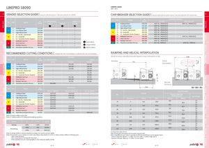
MILLINGOverviewFace millingHifeed millingShoulder millingProfile millingHardmillCenter & ChamferSpot faceEnd MillsSpare partsTechnical Data ap Pitch MILLINGOverviewFace millingHifeed millingShoulder millingProfile millingHardmillCenter & ChamferSpot faceEnd MillsSpare partsTechnical Data LINEPRO 18090 LINEPRO 18090APKT | APHT A grades selection guide | Guia para selecção de graus | Tabla para selección de calidades CHIP-BREAKER selection guide | Guia para aplicações do quebra-aparas | Guía para aplicación del rompevirutas A GradesISOPSMMaterialHBWear ResistanceToughness(Brinell)PH0910PH7(6)920PH7 (6)30 ISO PSM Material HB(Brinell) Chip-Breaker Application1st choiseDificult Operations1Unalloyed Steel125-220APKT 16… PDER-X(X2)APKT 16… PDSR-X(-X2) P 2 Low-Alloyed Steel 220-280 APKT 16… PDSR-X(X2) - 1 Unalloyed Steel 125-220 ✓ ✓ 3 High-Alloyed Steel 280-380 APKT 16… PDSR-X(X2) - P 2 Low-Alloyed Steel 220-280 ✓ ✓ 4 SS - Ferritic / Martensitic 200-330 APKT 16… PDER-X(X2) - 3 High-Alloyed Steel 280-380 ✓ ✓ M 5 SS - Austenitic 200-330 APKT 16… PDER-X(X2) - 4 SS - Ferritic / Martensitic 200-330 ✓ 6 SS - Austenitic-ferritic (Duplex) 230-260 APKT 16… PDSR-X(X2) - M 5 SS - Austenitic 200-330 ✓ 7 Malleable Cast Iron 130-230 APKT 16… PDSR-X(X2) APKT 16… PDSR-X(X2) 6 SS - Austenitic-ferritic (Duplex) 230-260 ✓ K 8 Grey Cast Iron 180-245 APKT 16… PDSR-X(X2) - 7 Malleable Cast Iron 130-230K8Grey Cast Iron180-245 ✓ ✓ Good Conditions✓✓ 9 Nodular Cast iron 160-250 APKT 16… PDSR-X(X2) -N10Aluminium and Non Ferrous30-130AP...T 16… PDFR-LNAPHT 16.... PDFR-LN 9 Nodular Cast iron 160-250 ✓ ✓ Average Conditions N 10 Aluminium and Non Ferrous 30-130 ✓ Difficult Conditions recommended cutting conditions | Condições de corte recomendadas | Condiciones de corte recomendables RAMPING AND HELICAL INTERPOLATION Vc (m/min) Descida em rampa e interpolação helicoidal | Bajada en rampa e interpolación circular DH ISO PSM Material HB(Brinell) Wear Resistance ToughnessPH0910PH7(6)920PH7(6)930 Ramping Lr1Unalloyed Steel125-220-150-230150-180 HelicalInterpolation P 2 Low-Alloyed Steel 220-280 - 140-220 140-170 3 High-Alloyed Steel 280-380 - 130-180 120-150 4 SS - Ferritic / Martensitic 200-330 - - 90-150 M 5 SS - Austenitic 200-330 - - 80-130 6 SS - Austenitic-ferritic (Duplex) 230-260 - - 70-100 7 Malleable Cast Iron 130-230 - 150-280 80-230 K 8 Grey Cast Iron 180-245 - 130-230 120-225 9 Nodular Cast iron 160-250 - 80-190 80-180N10Aluminium and Non Ferrous30-130350-1400-- Blind hole Flat bottom ISO PSM Material HB(Brinell) Feed fz (mm/t) Dc Ødi = ØDH - ØDc APKT 16… PDER-X/X2 APKT 16… PDS(T)R-X/X2 AP...T 16... PDFR-LN Helical Interpolation 1 Unalloyed Steel 125-220 0,07-0,15 0,10-0,25 -P2Low-Alloyed Steel220-2800,07-0,100,10-0,20-3High-Alloyed Steel280-3800,07-0,100,10-0,20-4SS - Ferritic / Martensitic200-3300,07-0,10--M5SS - Austenitic200-3300,07-0,10--RampingØDcDiameter for Blind Hole,Flat Bottom Face (1)Max Pitch/Rev.Max Ramp aºMax apMin LrØDHminØDHmax25314,5276,746,1--48,43,53,9 6 SS - Austenitic-ferritic (Duplex) 230-260 0,07-0,10 - -7Malleable Cast Iron130-2300,07-0,150,10-0,25- 32 2 14,5 415,2 60,1- -62,4 3,13,3 K 8 Grey Cast Iron 180-245 0,07-0,15 0,10-0,25 -9Nodular Cast iron160-250-0,10-0,20- 40 1,5 14,5 553,7 76,1- -78,4 3,03,2 N 10 Aluminium and Non Ferrous 30-130 - - 0,07-0,20 50 1,1 14,5 755,2 96,1- -98,4 2,82,9 (Note 1) Cutting conditions ae/Dc=70%.(Note 2) Cutting conditions for slotting and shouldering operations: 63 0,85 14,5 977,3 122,1- -124,4 2,82,9 Operation ae Vc & fz ap (mm) 80 0,64 14,5 1298,1 156,1- -158,4 2,72,7 Slotting 100% <20% 5,0-6,0 100 0,5 14,5 1661,5 196,1- -198,4 2,62,7 <50% >8% 6,0-9,0Shouldering25%>12%10,0-12,5 125 0,38 14,5 2186,3 246,1- -248,4 2,52,6 (1) Using insert radius 0,8 mm (Note 3) Cutting conditions should be adjusted according to the machine and work rigidity. Note: During helical interpolation do not exceed maximum pitch (Note 4) It’s possible to occur vibrations in certain cases. Please reduce depth of cut and / or reduce cutting conditions in following cases: When using different insert radius to calculate the ØDHmin and ØDHmax use the equation below: - When using long shank; - Minimum Diameter: ØDHmin = 2 x (ØDc - (R corner radius + F width of edge wiper)) - When using long tool overhang with arbor type; - Maximum Diameter: ØDHmax = 2 x (ØDc - R corner radius) - When application has poor clamping rigidity or when using a low rigidity machine. page A-236 page A -244 page A-236 page A -244 A - 172 A - 173