Общий каталог Palbit - страница 123
Навигация
 Общий каталог Palbit 2022
- General Catalogue
- Index
- NEWS
- MILLING
- Milling tool selection
- Tools Overview
- Inserts Codification
- New grade PHS
- Inserts Overview
- Face Milling
- PLUS 28088
- PLUS 90260
- PLUS 90845
- PLUS 90945
- PLUS 91245
- LINEPRO 06045
- LINEPRO 09945
- LINEPRO 00036
- Hifeed Milling
- PENTA HIFEED 06320
- HIFEED 06410
- HIFEED 06690
- HIFEED 06815
- HIFEED 50560
- HIFEED 50060
- HIFEED 06590
- Shoulder Milling
- PLUS 49090
- PLUS 17190
- PLUS 17590
- PLUS 18190
- LINEPRO 20090
- LINEPRO 20190
- LINEPRO 20290
- TGPLUS 90090
- TGPLUS 90190
- TGPLUS 90390
- ALUPRO 76090
- ALUPRO 77090
- ALUPRO 08390
- LINEPRO 06290
- LINEPRO 17090
- LINEPRO 18090
- LINEPRO 15090
- Profile Milling
- PLUS 49095
- PLUS 45095
- TOROMILL 33590|33690|33790
- TOROMILL 33890|33990
- TOROMILL X2 35190
- TOROMILL 24590|25090|25190
- TOROMILL 25290|25390
- LINEPRO 40095|40595|41095
- Hardmill
- HARDMILL 72090
- Center & Chamfer
- Spot face
- End Mills Carbide
- Straight Flutes PCD
- Solide Carbide End Mills
- Selection Guide for Solid Carbide
- HF30G S/XL
- HB30G S/L
- HB30G L
- HF 45G S
- HC45FL
- HF30HL
- HB30HL
- HC35ML
- HC38AS
- Technical Data
- Troubleshooting
- Spare Parts
- Procedures for clamping screws
- Technical Data
- Milling Grades
- Comparative Grades Chart
- Formulas & calculations
- Troubleshooting
- DRILLING
- Drills Code Key
- Nomenclature
- Overview
- Jet Drills
- Integrex Drills
- Vortex Drills
- Trepanning Drills
- Solid Carbide Drills
- ISO Driling inserts code key
- Inserts
- Spare Parts
- Technical Data
- TURNING
- New turning grades
- ISO Turning Code key
- Negative Inserts Overview
- Positive Inserts Overview
- Negative Inserts
- CN Inserts
- CNMA
- CNMG-SF
- CNMG-LC
- CNMG-MS
- CNMG-MR
- CNMG-PM
- CNMG-ST
- CNMM-RP
- CNMM-HY
- CNMM-HZ
- DN Inserts
- DNMA
- DNMG-MF
- DNMG-SF
- DNMG-LC
- DNMG-MS
- DNMG-MR
- DNMG-PM
- DNMG-ST
- DNMG-MW
- DNMG-SS
- DNMG-HR
- DNMM-RP
- DNMX-02
- DNMX-03
- DNMX-01
- KN Inserts
- KNUX-01
- KNUX-02
- RN Inserts
- RNMA
- RNMG-ST
- SN Inserts
- SNMA
- SNMG-MF
- SNMG-SF
- SNMG-MR
- SNMG-PM
- SNMG-ST
- SNMG-SS
- SNMG-HR
- SNMM-RP
- SNMM-HY
- SNMM-HZ
- SNGN
- SNUN
- TN Inserts
- TNMA
- TNMG-MF
- TNMG-MS
- TNMG-MR
- TNMG-PM
- TNMG-ST
- TNMG-MW
- TNMG-SS
- TNMG-HR
- TNMX-01
- VN Inserts
- VNMA
- VNMG-MF
- VNMG-SF
- VNMG-LC
- VNMG-MS
- VNMG-MR
- VNMG-PM
- VNMG-ST
- VNMG-SS
- WN Inserts
- WNMA
- WNMG-MF
- WNMG-SF
- WNMG-LC
- WNMG-MS
- WNMG-PM
- WNMG-MR
- WNMG-ST
- WNMG-MW
- WNMG-SS
- WNMG-HR
- Positive Inserts
- CC Inserts
- CCMW
- CCMT-FP
- CCMT-BO
- CCMT-FM
- CCMT-FK
- CCMT-FW
- CCMT-LM
- CCMT-MP
- CCMT-MM
- CCMT-MK
- CCMT-MW
- CCGT-FS
- CCGT-LN
- DC Inserts
- DCMW
- DCMT-FP
- DCMT-FM
- DCMT-FK
- DCMT-FW
- DCMT-LM
- DCMT-MP
- DCMT-MM
- DCMT-MK
- DCMT-MW
- DCGT-FS
- DCGT-LN
- RC Inserts
- RCMT-CP
- RCMT-ST
- RCMT-RF
- RCMT-RM
- RCMX-ST
- RCMX-RM
- RCMX-RR
- RCGT-LN
- SC Inserts
- SCMW
- SCMT-FP
- SCMT-FM
- SCMT-FK
- SCMT-MP
- SCMT-MM
- SCMT-MK
- SCGT-LN
- SP Inserts
- SPUN
- SPMR-12
- SPMR-13
- TC Inserts
- TCMW
- TCMT-FP
- TCMT-FM
- TCMT-FK
- TCMT-FW
- TCMT-MP
- TCMT-MM
- TCMT-MK
- TCMT-MW
- TCGT-FS
- TCGT-LN
- TP Inserts
- TPUN
- TPMR-12
- TPMR-13
- VB Inserts
- VBMW
- VBMT-FP
- VBMT-FM
- VBMT-FK
- VBMT-MP
- VBMT-MM
- VBMT-MK
- VC Inserts
- VCMW
- VCMT-FP
- VCMT-FM
- VCMT-FK
- VCMT-MP
- VCMT-MM
- VCMT-MK
- VCGT-FS
- VCGT-LN
- PCD Inserts
- PCD Inserts selection
- ISO PCD Inserts code key
- Single Tip
- Negative Inserts
- CNGA Z1
- DNGA Z1
- SNGA Z1
- TNGA Z1
- VNGA Z1
- Positive Inserts
- OVERVIEW
- CCGT Z1
- CCGW Z1
- CPGT Z1
- CPGW Z1
- DCGT Z1
- DCGW Z1
- SCGT Z1
- SCGW Z1
- VCGT Z1
- VCGW Z1
- TCGT Z1
- TCGW Z1
- TPGT Z1
- TPGW Z1
- Full Edge - Positive Inserts
- CCGT FR/FL
- CCGW FR/FL
- TCGT FL
- TCGW FL
- PCD recommended cutting data
- Heavy machinning
- Bar Peeling
- Inserts code key
- Negative Inserts
- INGR-MP
- JNGF-MP
- LNGF-MP
- UNGF-MP
- TNMJ-MP
- TNGM-MP
- TNMM-LH
- XNMJ-MP
- XNMJ-MH
- XNGJ-RP
- WNGJ-MP
- RNMX-MP
- RNMX-RP
- RNMG-ST
- Railway Turning
- Inserts code key
- Negative Inserts
- CNMM-HY
- CNMM-HZ
- SNMM-HY
- SNMM-HZ
- LNUX-RMM
- LNUX-RRM
- LNUX-RHR
- LNUX-RMM-T
- LNUX-RRM-T
- LNUX-RHR-T
- Positive Inserts
- RCMR-RR
- RCMX-ST
- RCMX-RM
- RCMX-RR
- External Toolholders
- External toolholder code key
- Clamping System
- (C) Top Clamping Toolholders
- CKJN 93º
- CKNN 63º
- CSBP 75º
- CSDP 45º
- CSKP 75º
- CSSP 45º
- CSTP 60º
- CTBP 75º
- CTCP N 90º
- CTCP 90º
- CTDP 45º
- CTFP 90º
- CTGP 90º
- CTTP 60º
- (D) Dimple Lock Toolholders
- DCLN 95º
- DDJN 93º
- DSSN 45º
- DTGN 90º
- DWLN 95º
- (M) Wedge Clamp Toolholders
- MCLN 95º
- MSSN 45º
- MTEN 60º
- MTJN 93º
- MTNN 63º
- MWLN 95º
- (M-K) Double Lock Toolholders
- MCLN-K 95º
- MDJN-K 93º
- MSSN-K 45º
- MTJN-K 93º
- MVJN-K 93º
- MVQN-K 117º30’
- MVVN-K 72º30’
- MWLN-K 95º
- (P) Lever LockToolholders
- PCBN 75º
- PCFN 90º
- PCKN 75º
- PCLN 95º
- PCMN 50º
- PCSN 45º
- PDJN 93º
- PDNN 63º
- PRDC
- PRSC
- PRSN
- PSBN 75º
- PSDN 45º
- PSKN 75º
- PSSN 45º
- PTDN 45º
- PTFN 90º
- PTGN 90º
- PTTN 60º
- PWLN 95º
- (S) Center Screw Toolholders
- SCAC 90º
- SCLC 95º
- SDJC 93º
- SDNC 62º30’
- SRDC
- SSBC 75º
- SSDC 45º
- SSSC 45º
- STAC 90º
- STDC 45º
- STFC 90º
- STGC 90º
- STJC 93º
- STTC 60º
- SVHC 107º30’
- SVJB 93º
- SVJC 93º
- SVLC 95º
- SVVB 72º30’
- SVVC 72º30’
- SVXC 113º
- SVZC 100º
- Internal Toolholders
- Clamping System
- (C) Top Clamp Toolholders
- CKUN 93º
- CSKP 75º
- CTFP 90º
- CTUP 93º
- (D) Dimple Lock Toolholders
- DCLN 95º
- DDUN 93º
- (M) Wedge Clamp Toolholders
- MTUN 93º
- MWLN 95º
- (M-K) Double Lock Toolholders
- MCLN-K 95º
- MDUN-K 93º
- MSKN-K 75º
- MTFN 90º
- MTFN-K 90º
- MVUN-K 93º
- MWLN-K 95º
- (P) Lever Lock Toolholders
- PCKN 75º
- PCLN 95º
- A-PCLN 95º
- PDUN 93º
- A-PDUN 93º
- PDUN 93º-BT
- PSKN 75º
- A-PSKN 75º
- A-PSSN 45º
- PTFN 90º
- A-PTFN 90º
- PWLN 95º
- A-PWLN 95º
- (S) Center Screw Toolholders
- SCLC 95º
- A-SCLC 95º
- E-SCLC 95º
- SCLC N 95º
- SDQC 107º30’
- A-SDQC 107º30’
- SDUC 93º
- A-SDUC 93º
- E-SDUC 93º
- SDUC 93º-BT
- A-SDUC 93º-BT
- SSKC 75º
- A-SSSC 45º
- STFC 90º
- A-STFC 90º
- E-STFC 90º
- STUC 93º
- SVQC 107º30’
- A-SVQC 107º30’
- SVUB 93º
- SVUC 93º
- A-SVUC 93º
- A-SVJC 93º
- Anti-vibrations Toolholders
- BAV | toolholders
- (M) Wedge Clamp Toolholders
- MTUN 93º
- (P) Lever Lock Toolholders
- PCLN 95º
- PDUN 93º
- PWLN 95º
- (S) Center Screw Toolholders
- SCLC 95º
- SDUC 93º
- STFC 90º
- Internal Toolholders Set
- PK SCLC 95º
- PK SDQC 107º30’
- PK SDUC 93º
- PK STFC 90º
- Automatic Lathes
- Automatic Lathes code key
- Overview
- Center Screw System (S)
- SCAC 90º
- SCLC 95º
- SDAC 90º
- SDJC 93º
- SDNC 62º30’
- STJC 93º
- SVAC 90º
- SVJC 93º
- SVVC 72º30’
- Spare Parts
- CHIP BREAKERS
- CLAMPS (C HOLDERS)
- DIFFERENTIALS SCREWS
- LEVERS
- LEVER SCREWS
- LOCK PINS
- SCREWS (TORX)
- SHIMS (V SHAPES)
- SHIMS (W SHAPES)
- SHIMS (KNUX SHAPES)
- SPRINGS
- WEDGE CLAMPS (M HOLDERS)
- WEDGE CLAMPS (M-K HOLDERS)
- WRENCHES (ALLEN)
- WRENCHES (TORKS)
- Technical Data
- Turning Grades
- Comparative Grades Chart
- Comparative Chip-breaker Chart
- Chip-breaker Specifications
- Cutting Speed
- Selection Guide
- Troubleshooting
- Wiper Concept
- GROOVING & PARTING OFF
- Inserts Overview
- Grooving Plus
- Inserts code key
- GP Inserts
- Blades & Toolholders code key
- Blades & Toolholders
- GP Toolholders
- Grooving
- Inserts code key
- Inserts Overview
- Inserts GCMX
- Inserts SANCAR
- Blades code key
- Blades
- Toolholders
- Trigon inserts code key
- Flat grooving inserts
- Full radius grooving inserts
- External toolholder code key
- External toolholder
- Internal toolholder code key
- Internal toolholder
- SAL
- Inserts code key
- Toolholders code key
- Toolholders
- Inserts
- Technical data
- Spare Parts
- Technical Data
- THREADING
- THREAD MILLING
- Inserts code key
- Inserts program
- iso
- un unc, unf, unef, uns
- whit bsw, bsf, bsp
- bspt
- npt
- nptf
- nps
- npsf
- pg din 40430
- unj
- american buttress
- acme
- Tooholders code key
- Multi insert toolholders
- Internal toolholders
- External toolholders
- Single insert toolholders
- wssn-1
- wssn-1 | Long shank
- ecsn-1 | Long carbide shank
- Double insert toolholders
- wssn-2
- Toolholders technical data
- Technical Data
- THREAD TURNING
- Threading - Step by Step Example
- Inserts Overview
- Partial Profile inserts
- Partial Profile code key
- Partial Profile 60º
- Partial profile 55º
- Full Profile inserts
- full profile inserts code key
- ISO METRIC ISO 965-1: 1999-11 | DIN 13: 2005-08
- AMERICAN UN (UNC, UNF, UNEF) | ANSI B1.1-1982
- WITHWORTH FOR BSW, BSF, BSP, B.S.84: 1956, DIN 259, ISO 228-1:1994
- BSPT | B.S.21: 1985
- NPT | ANSI/ASME B 1.20.1-1983
- NPTF | ANSI B 1.20.3-1976
- ROUND (DIN 405) | DIN 405:1997
- ROUND (DIN 20400) | DIN 20400:1990
- TRAPEZ | DIN 103:1977 | ISO 2901:1993
- AMERICAN ACME | ANSI/ASME: 1.5-1988
- STUB ACME | ANSI/ASME: 1.8-1988
- UNJ | MIL-S-8879A
- UNJ | MIL-S-8879A
- MJ | ISO 5855-1:1989
- AMERICAN BUTTRESS | ANSI B1.9-1973
- METRIC BUTTRESS SAGENGEWINDE (DIN 513:1985) SAW THREAD
- API | API SPEC 7:2001 (0.040 | 0.038r | 0.050)
- API | buttress casing | api spec 5b:2008 | oil threads
- API Round Casing & Tubing | API SPEC 5B:2008
- EXTREME LINE CASING | API SPEC 5B:2008 - OIL THREADS
- PG | DIN 40430; 1971
- Tangencial profile inserts
- Tangencial profile code key
- TNMC (Tangencial Inserts)
- TPMC (Tangencial Inserts)
- External Toolholders
- External toolholders code key
- STCN 90º
- SXAN
- Internal Toolholders
- Internal toolholders code key
- STGN 90º
- SXFN
- STGP 90º
- Spare Parts
- Technical Data
- GENERAL TECHNICAL DATA
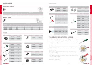
A ADJUSTMENT SCREW
L1 L Dimensions (mm)
order code Screw T (torx)
| M | ØD | L | L1 | ||||
| 290014200 | P0350750 | T-15 | M3,5 x 0,6 | 8,00 | 7,2 | 4,0 |
WASHER SCREW
L1
L Dimensions (mm) order code Screw
| M | ØD L | L1 | |
| P0401065 290075600 | M4 x 0,6 | 10,0 5,7 | 6,0 |
| P0601265 290018500 | M6 x 1,0 | 12,4 9,00 | 6,5 |
| P0601765 290011000 | M6 x 1,0 | 17,0 9,00 | 11,0 |
| P0802265 290028400 | M8 x 1,25 | 22,0 11,0 | 15,0 |
| otherS | |||
| Washer Order Code | Reference | Cartridge Screw Order Code | Reference |
| 290012100 | HC01200 | ||
| 119169600 | D0602096 | ||
| 290060200 | HC01400 | ||
| 290002900 | HC01800 | ||
| Torx Keys Order Code | Reference | Shim Order Code | Reference |
| XT 290058600 | XT 06IP | 212074100 | CS130300 |
| 290011400 | XT 06 | ||
| 290060400 | CT160300 | ||
| 290012900 | XT07 | ||
| 290060300 | CT220300 | ||
| PT 290011700 | XT 08 | ||
| 290025700 | XT 09 | ||
| Spring Pin Order Code | Reference | ||
| 290013100 | XT 10 | ||
| 290060600 | BE02500 | ||
| TT 290012400 | XT 15 | ||
| 290060500 | BE04000 | ||
| 290013200 | XT 20 | ||
| 290014800 | PT 15 | ||
| LT 290014900 | PT 20 | Wedge (Insert) Order Code | Reference |
| 290056000 | TT 20 | 290060900 | WA7001 |
| 290059500 | LT 30 | 290061100 | WA7003 |
Spot face
A
| Wedge (Cartridge) | Order Code | Reference | Cartridge | Order Code | Reference |
| 290061000 | WA7002 | 290060700 | KR030450 |
290061200 WA7004 290060800 KR040750
| Hex Key | Order Code | Reference | Tork Keys Order Code | Reference | Torx | Nm |
| 290078300 | DT0606IP | 6IP | 0,6 | |||
| SS | 290021200 | SS40 | ||||
| 290059600 | DT0606 | 6 | 0,6 | |||
| 290059700 | DT0709 | 7 | 0,9 | |||
| TS | 290021300 | SS50 | ||||
| 290059800 | DT0812 | 8 | 1,2 | |||
| 290058700 | TS40 | 290059900 | DT0914 | 9 | 1,4 | |
| 290060000 | DT1020 | 10 | 2,0 | |||
| 290047800 | DT1530 | 15 | 3,0 |
Screw for Coolant Order Code Reference M Ø Ext.
Supply 290078400 DT2050 20 5,0
| 119163000 | J0123510 | 12 | 37,9 | DIN 6368 Wrench | Order Code | Reference |
| 290058000 | SD6368-12 | |||||
| 119163100 | J0164110 | 16 | 45,0 | |||
| 290058100 | SD6368-16 | |||||
| 119163200 | J0204610 | 20 | 54,8 |
290058200 SD6368-20 Procedures for Clamping Screws 1. Always use a torque wrench to ensure that screws are correctly tightened (please confirm torques data on catalogue). Torque that is too high will negatively affect the performance of the
tool and can cause screw and insert breakage. Torque that is too low will cause insert movement, vibration and degrade the cutting result. Dedicated adjustable torque wrench can be ordered separately (please see above).
2. Clean the insert seat. Make sure that the insert seat is free from dust or chips from the machining. If necessary, clean the insert seat with compressed air.
3. Check the insert seat. Before assembly cutter it is important to ensure that the insert seat has not been damaged during machining or handling.
4. Apply sufficient screw lubrication to prevent seizure. Lubricant should be applied to the screw threads as well as to the screw head face.
5. Replace worn or damaged screws.