Общий каталог Palbit - страница 17
Навигация
 Общий каталог Palbit 2022
- General Catalogue
- Index
- NEWS
- MILLING
- Milling tool selection
- Tools Overview
- Inserts Codification
- New grade PHS
- Inserts Overview
- Face Milling
- PLUS 28088
- PLUS 90260
- PLUS 90845
- PLUS 90945
- PLUS 91245
- LINEPRO 06045
- LINEPRO 09945
- LINEPRO 00036
- Hifeed Milling
- PENTA HIFEED 06320
- HIFEED 06410
- HIFEED 06690
- HIFEED 06815
- HIFEED 50560
- HIFEED 50060
- HIFEED 06590
- Shoulder Milling
- PLUS 49090
- PLUS 17190
- PLUS 17590
- PLUS 18190
- LINEPRO 20090
- LINEPRO 20190
- LINEPRO 20290
- TGPLUS 90090
- TGPLUS 90190
- TGPLUS 90390
- ALUPRO 76090
- ALUPRO 77090
- ALUPRO 08390
- LINEPRO 06290
- LINEPRO 17090
- LINEPRO 18090
- LINEPRO 15090
- Profile Milling
- PLUS 49095
- PLUS 45095
- TOROMILL 33590|33690|33790
- TOROMILL 33890|33990
- TOROMILL X2 35190
- TOROMILL 24590|25090|25190
- TOROMILL 25290|25390
- LINEPRO 40095|40595|41095
- Hardmill
- HARDMILL 72090
- Center & Chamfer
- Spot face
- End Mills Carbide
- Straight Flutes PCD
- Solide Carbide End Mills
- Selection Guide for Solid Carbide
- HF30G S/XL
- HB30G S/L
- HB30G L
- HF 45G S
- HC45FL
- HF30HL
- HB30HL
- HC35ML
- HC38AS
- Technical Data
- Troubleshooting
- Spare Parts
- Procedures for clamping screws
- Technical Data
- Milling Grades
- Comparative Grades Chart
- Formulas & calculations
- Troubleshooting
- DRILLING
- Drills Code Key
- Nomenclature
- Overview
- Jet Drills
- Integrex Drills
- Vortex Drills
- Trepanning Drills
- Solid Carbide Drills
- ISO Driling inserts code key
- Inserts
- Spare Parts
- Technical Data
- TURNING
- New turning grades
- ISO Turning Code key
- Negative Inserts Overview
- Positive Inserts Overview
- Negative Inserts
- CN Inserts
- CNMA
- CNMG-SF
- CNMG-LC
- CNMG-MS
- CNMG-MR
- CNMG-PM
- CNMG-ST
- CNMM-RP
- CNMM-HY
- CNMM-HZ
- DN Inserts
- DNMA
- DNMG-MF
- DNMG-SF
- DNMG-LC
- DNMG-MS
- DNMG-MR
- DNMG-PM
- DNMG-ST
- DNMG-MW
- DNMG-SS
- DNMG-HR
- DNMM-RP
- DNMX-02
- DNMX-03
- DNMX-01
- KN Inserts
- KNUX-01
- KNUX-02
- RN Inserts
- RNMA
- RNMG-ST
- SN Inserts
- SNMA
- SNMG-MF
- SNMG-SF
- SNMG-MR
- SNMG-PM
- SNMG-ST
- SNMG-SS
- SNMG-HR
- SNMM-RP
- SNMM-HY
- SNMM-HZ
- SNGN
- SNUN
- TN Inserts
- TNMA
- TNMG-MF
- TNMG-MS
- TNMG-MR
- TNMG-PM
- TNMG-ST
- TNMG-MW
- TNMG-SS
- TNMG-HR
- TNMX-01
- VN Inserts
- VNMA
- VNMG-MF
- VNMG-SF
- VNMG-LC
- VNMG-MS
- VNMG-MR
- VNMG-PM
- VNMG-ST
- VNMG-SS
- WN Inserts
- WNMA
- WNMG-MF
- WNMG-SF
- WNMG-LC
- WNMG-MS
- WNMG-PM
- WNMG-MR
- WNMG-ST
- WNMG-MW
- WNMG-SS
- WNMG-HR
- Positive Inserts
- CC Inserts
- CCMW
- CCMT-FP
- CCMT-BO
- CCMT-FM
- CCMT-FK
- CCMT-FW
- CCMT-LM
- CCMT-MP
- CCMT-MM
- CCMT-MK
- CCMT-MW
- CCGT-FS
- CCGT-LN
- DC Inserts
- DCMW
- DCMT-FP
- DCMT-FM
- DCMT-FK
- DCMT-FW
- DCMT-LM
- DCMT-MP
- DCMT-MM
- DCMT-MK
- DCMT-MW
- DCGT-FS
- DCGT-LN
- RC Inserts
- RCMT-CP
- RCMT-ST
- RCMT-RF
- RCMT-RM
- RCMX-ST
- RCMX-RM
- RCMX-RR
- RCGT-LN
- SC Inserts
- SCMW
- SCMT-FP
- SCMT-FM
- SCMT-FK
- SCMT-MP
- SCMT-MM
- SCMT-MK
- SCGT-LN
- SP Inserts
- SPUN
- SPMR-12
- SPMR-13
- TC Inserts
- TCMW
- TCMT-FP
- TCMT-FM
- TCMT-FK
- TCMT-FW
- TCMT-MP
- TCMT-MM
- TCMT-MK
- TCMT-MW
- TCGT-FS
- TCGT-LN
- TP Inserts
- TPUN
- TPMR-12
- TPMR-13
- VB Inserts
- VBMW
- VBMT-FP
- VBMT-FM
- VBMT-FK
- VBMT-MP
- VBMT-MM
- VBMT-MK
- VC Inserts
- VCMW
- VCMT-FP
- VCMT-FM
- VCMT-FK
- VCMT-MP
- VCMT-MM
- VCMT-MK
- VCGT-FS
- VCGT-LN
- PCD Inserts
- PCD Inserts selection
- ISO PCD Inserts code key
- Single Tip
- Negative Inserts
- CNGA Z1
- DNGA Z1
- SNGA Z1
- TNGA Z1
- VNGA Z1
- Positive Inserts
- OVERVIEW
- CCGT Z1
- CCGW Z1
- CPGT Z1
- CPGW Z1
- DCGT Z1
- DCGW Z1
- SCGT Z1
- SCGW Z1
- VCGT Z1
- VCGW Z1
- TCGT Z1
- TCGW Z1
- TPGT Z1
- TPGW Z1
- Full Edge - Positive Inserts
- CCGT FR/FL
- CCGW FR/FL
- TCGT FL
- TCGW FL
- PCD recommended cutting data
- Heavy machinning
- Bar Peeling
- Inserts code key
- Negative Inserts
- INGR-MP
- JNGF-MP
- LNGF-MP
- UNGF-MP
- TNMJ-MP
- TNGM-MP
- TNMM-LH
- XNMJ-MP
- XNMJ-MH
- XNGJ-RP
- WNGJ-MP
- RNMX-MP
- RNMX-RP
- RNMG-ST
- Railway Turning
- Inserts code key
- Negative Inserts
- CNMM-HY
- CNMM-HZ
- SNMM-HY
- SNMM-HZ
- LNUX-RMM
- LNUX-RRM
- LNUX-RHR
- LNUX-RMM-T
- LNUX-RRM-T
- LNUX-RHR-T
- Positive Inserts
- RCMR-RR
- RCMX-ST
- RCMX-RM
- RCMX-RR
- External Toolholders
- External toolholder code key
- Clamping System
- (C) Top Clamping Toolholders
- CKJN 93º
- CKNN 63º
- CSBP 75º
- CSDP 45º
- CSKP 75º
- CSSP 45º
- CSTP 60º
- CTBP 75º
- CTCP N 90º
- CTCP 90º
- CTDP 45º
- CTFP 90º
- CTGP 90º
- CTTP 60º
- (D) Dimple Lock Toolholders
- DCLN 95º
- DDJN 93º
- DSSN 45º
- DTGN 90º
- DWLN 95º
- (M) Wedge Clamp Toolholders
- MCLN 95º
- MSSN 45º
- MTEN 60º
- MTJN 93º
- MTNN 63º
- MWLN 95º
- (M-K) Double Lock Toolholders
- MCLN-K 95º
- MDJN-K 93º
- MSSN-K 45º
- MTJN-K 93º
- MVJN-K 93º
- MVQN-K 117º30’
- MVVN-K 72º30’
- MWLN-K 95º
- (P) Lever LockToolholders
- PCBN 75º
- PCFN 90º
- PCKN 75º
- PCLN 95º
- PCMN 50º
- PCSN 45º
- PDJN 93º
- PDNN 63º
- PRDC
- PRSC
- PRSN
- PSBN 75º
- PSDN 45º
- PSKN 75º
- PSSN 45º
- PTDN 45º
- PTFN 90º
- PTGN 90º
- PTTN 60º
- PWLN 95º
- (S) Center Screw Toolholders
- SCAC 90º
- SCLC 95º
- SDJC 93º
- SDNC 62º30’
- SRDC
- SSBC 75º
- SSDC 45º
- SSSC 45º
- STAC 90º
- STDC 45º
- STFC 90º
- STGC 90º
- STJC 93º
- STTC 60º
- SVHC 107º30’
- SVJB 93º
- SVJC 93º
- SVLC 95º
- SVVB 72º30’
- SVVC 72º30’
- SVXC 113º
- SVZC 100º
- Internal Toolholders
- Clamping System
- (C) Top Clamp Toolholders
- CKUN 93º
- CSKP 75º
- CTFP 90º
- CTUP 93º
- (D) Dimple Lock Toolholders
- DCLN 95º
- DDUN 93º
- (M) Wedge Clamp Toolholders
- MTUN 93º
- MWLN 95º
- (M-K) Double Lock Toolholders
- MCLN-K 95º
- MDUN-K 93º
- MSKN-K 75º
- MTFN 90º
- MTFN-K 90º
- MVUN-K 93º
- MWLN-K 95º
- (P) Lever Lock Toolholders
- PCKN 75º
- PCLN 95º
- A-PCLN 95º
- PDUN 93º
- A-PDUN 93º
- PDUN 93º-BT
- PSKN 75º
- A-PSKN 75º
- A-PSSN 45º
- PTFN 90º
- A-PTFN 90º
- PWLN 95º
- A-PWLN 95º
- (S) Center Screw Toolholders
- SCLC 95º
- A-SCLC 95º
- E-SCLC 95º
- SCLC N 95º
- SDQC 107º30’
- A-SDQC 107º30’
- SDUC 93º
- A-SDUC 93º
- E-SDUC 93º
- SDUC 93º-BT
- A-SDUC 93º-BT
- SSKC 75º
- A-SSSC 45º
- STFC 90º
- A-STFC 90º
- E-STFC 90º
- STUC 93º
- SVQC 107º30’
- A-SVQC 107º30’
- SVUB 93º
- SVUC 93º
- A-SVUC 93º
- A-SVJC 93º
- Anti-vibrations Toolholders
- BAV | toolholders
- (M) Wedge Clamp Toolholders
- MTUN 93º
- (P) Lever Lock Toolholders
- PCLN 95º
- PDUN 93º
- PWLN 95º
- (S) Center Screw Toolholders
- SCLC 95º
- SDUC 93º
- STFC 90º
- Internal Toolholders Set
- PK SCLC 95º
- PK SDQC 107º30’
- PK SDUC 93º
- PK STFC 90º
- Automatic Lathes
- Automatic Lathes code key
- Overview
- Center Screw System (S)
- SCAC 90º
- SCLC 95º
- SDAC 90º
- SDJC 93º
- SDNC 62º30’
- STJC 93º
- SVAC 90º
- SVJC 93º
- SVVC 72º30’
- Spare Parts
- CHIP BREAKERS
- CLAMPS (C HOLDERS)
- DIFFERENTIALS SCREWS
- LEVERS
- LEVER SCREWS
- LOCK PINS
- SCREWS (TORX)
- SHIMS (V SHAPES)
- SHIMS (W SHAPES)
- SHIMS (KNUX SHAPES)
- SPRINGS
- WEDGE CLAMPS (M HOLDERS)
- WEDGE CLAMPS (M-K HOLDERS)
- WRENCHES (ALLEN)
- WRENCHES (TORKS)
- Technical Data
- Turning Grades
- Comparative Grades Chart
- Comparative Chip-breaker Chart
- Chip-breaker Specifications
- Cutting Speed
- Selection Guide
- Troubleshooting
- Wiper Concept
- GROOVING & PARTING OFF
- Inserts Overview
- Grooving Plus
- Inserts code key
- GP Inserts
- Blades & Toolholders code key
- Blades & Toolholders
- GP Toolholders
- Grooving
- Inserts code key
- Inserts Overview
- Inserts GCMX
- Inserts SANCAR
- Blades code key
- Blades
- Toolholders
- Trigon inserts code key
- Flat grooving inserts
- Full radius grooving inserts
- External toolholder code key
- External toolholder
- Internal toolholder code key
- Internal toolholder
- SAL
- Inserts code key
- Toolholders code key
- Toolholders
- Inserts
- Technical data
- Spare Parts
- Technical Data
- THREADING
- THREAD MILLING
- Inserts code key
- Inserts program
- iso
- un unc, unf, unef, uns
- whit bsw, bsf, bsp
- bspt
- npt
- nptf
- nps
- npsf
- pg din 40430
- unj
- american buttress
- acme
- Tooholders code key
- Multi insert toolholders
- Internal toolholders
- External toolholders
- Single insert toolholders
- wssn-1
- wssn-1 | Long shank
- ecsn-1 | Long carbide shank
- Double insert toolholders
- wssn-2
- Toolholders technical data
- Technical Data
- THREAD TURNING
- Threading - Step by Step Example
- Inserts Overview
- Partial Profile inserts
- Partial Profile code key
- Partial Profile 60º
- Partial profile 55º
- Full Profile inserts
- full profile inserts code key
- ISO METRIC ISO 965-1: 1999-11 | DIN 13: 2005-08
- AMERICAN UN (UNC, UNF, UNEF) | ANSI B1.1-1982
- WITHWORTH FOR BSW, BSF, BSP, B.S.84: 1956, DIN 259, ISO 228-1:1994
- BSPT | B.S.21: 1985
- NPT | ANSI/ASME B 1.20.1-1983
- NPTF | ANSI B 1.20.3-1976
- ROUND (DIN 405) | DIN 405:1997
- ROUND (DIN 20400) | DIN 20400:1990
- TRAPEZ | DIN 103:1977 | ISO 2901:1993
- AMERICAN ACME | ANSI/ASME: 1.5-1988
- STUB ACME | ANSI/ASME: 1.8-1988
- UNJ | MIL-S-8879A
- UNJ | MIL-S-8879A
- MJ | ISO 5855-1:1989
- AMERICAN BUTTRESS | ANSI B1.9-1973
- METRIC BUTTRESS SAGENGEWINDE (DIN 513:1985) SAW THREAD
- API | API SPEC 7:2001 (0.040 | 0.038r | 0.050)
- API | buttress casing | api spec 5b:2008 | oil threads
- API Round Casing & Tubing | API SPEC 5B:2008
- EXTREME LINE CASING | API SPEC 5B:2008 - OIL THREADS
- PG | DIN 40430; 1971
- Tangencial profile inserts
- Tangencial profile code key
- TNMC (Tangencial Inserts)
- TPMC (Tangencial Inserts)
- External Toolholders
- External toolholders code key
- STCN 90º
- SXAN
- Internal Toolholders
- Internal toolholders code key
- STGN 90º
- SXFN
- STGP 90º
- Spare Parts
- Technical Data
- GENERAL TECHNICAL DATA
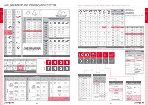
MILLINGOverviewFace millingHifeed millingShoulder millingProfile millingHardmillCenter & ChamferSpot faceEnd MillsSpare partsTechnical Data symbol with hole Symbol symbol with hole ISOANSI symbol with holewithout hole MILLINGOverviewFace millingHifeed millingShoulder millingProfile millingHardmillCenter & ChamferSpot faceEnd MillsSpare partsTechnical Data milling inserts iso identification system Sistema de identificação ISO para pastilhas de fixação mecânica | Codificación ISO para insertos indexables A * ANSI designation onlyØ CIANSI(Radius Designation is 00) A H M m m ** Metric designation only R’s V’s D’s C’s S’s T’s W’s mm inch Symbol (Radius Designation is M0) d d SO135ºV Triangular inserts with a facet(secondary cutting edge) - 06 04 - 03 06 02 3,97 5/32 1,20 According to International Standard ISO 1832 - 2012(E)-0805040408L34,763/161,50“Indexable inserts for cutting tools - Designation” m (mm) d (mm) s (mm) Detailed dimension of M class insertInsert height Tolerances (mm) - 09 06 05 05 09 03 5,56 7/32 1,80 06** - - - - - - 6,00 0,236 P W A ±0.005 ±0.025 ±0.025 Inscrebed 06* 11 07 06 06 11 04 6,35 1/4 2,00 F ±0.005 ±0.013 ±0.025 circle 07* 13 09 08 07 13 05 7,94 5/16 2,50 C ±0.013 ±0.025 ±0.025 6.35 ±0.08 - - - - 08* - - - - - - 8,00 0,315 S L H ±0.013 ±0.013 ±0.025 9.525 ±0.08 ±0.08 ±0.11 ±0.10 ±0.13 09* 16 11 09 09 16 06 9,525 3/8 3,00 ISO mm ANSI inch E ±0.025 ±0.025 ±0.025 12.70 ±0.13 ±0.13 ±0.13 ±0.15 - 10** - - - - - - 10,00 0,394 01 1.59 1 0.062 G ±0.025 ±0.025 ±0.13 15.875 ±0.15 ±0.15 ±0.15 ±0.18 - 12** - - - - - - 12,00 0,472 T1 1.98 1.2 0.078 T A J ±0.005 ±0.05~±0.13 ±0.025 19.05 ±0.15 ±0.15 ±0.15 ±0.18 - 12* 22 15 12 12 22 08 12,70 1/2 4,00 02 2.38 1.5 0.094 K* ±0.013 ±0.05~±0.13 ±0.025 25.40 - ±0.18 - - - 15* 27 19 16 15 27 10 15,875 5/8 5,00 03 3.18 2 0.125 16** - - - - - - 16,00 0,63 T3 3.97 2.5 0.156 C B L* ±0.025 ±0.05~±0.13 ±0.025 31.75 - ±0.25 - - -M*±0.08~±0.20±0.05~±0.13±0.13Inscribed circle Tolerances (mm)19*33 23 19 19 33 13 19,05 3/4 6,00 04 4.76 3 0.18820**------20,000,787055.563.50.219 N* ±0.08~±0.20 ±0.05~±0.13 ±0.025 Inscrebed 25** - - - - - - 25,00 0,984 06 6.35 4 0.250 D K U* ±0.13~±0.38 ±0.08~±0.25 ±0.13 circle 25* 44 31 25 25 44 17 25,40 1,00 8,00 07 7.94 5 0.312 6.35 ±0.05 - - - - 31* 54 38 32 31 54 21 31,75 1 1/4 10,00 09 9.52 6 0.375 9.525 ±0.05 ±0.05 ±0.05 ±0.05 ±0.05 32** - - - - - - 32,00 1,26 12 12.70 8 0.500 E R *As a rule, the sides of these inserts are 12.70 ±0.08 ±0.08 ±0.08 ±0.08 ±0.08as sintered. Tolerance differs with insertsize, for the accuracy of class M, refer to15.875±0.10±0.10±0.10±0.10±0.105 - Insert size symbol 6 - Insert thickness symbol the table on the right. 19.05 - - - - ±0.10 10 - Chipbreaker geometries F 1- Insert shape symbol 25.40 - ±0.13 - - ±0.1031.75-±0.20--±0.123 - Tolerances symbol16 03 08AN E N MP Cutting Condition Main Application1st letter2nd letter L - Light P - Steel A B C D E T N G N 3 2 2 E N MP M - Medium M - Stainless SteelH - HeavyK - Cast Iron 3º 5º 7º 15º 20º F G N P O W - Wiper N - Aluminium Otherclearance angle T N G N S - HRSA*only whenTitanium Alloys 2 - Normal clearance symbol required. H - Hardened Materials 7 - Insert corner symbol 7.1* - Insert edges symbol Ex.: ANHX 160708 PNER - MP 4 - Insert symbol ISO mm inch ANSI For inserts having secondary 00 Sharp nose 0 edges two digits are used: Type Hole type Chipbreaker Shape Type Hole type Chipbreaker Shape Type Hole type Chipbreaker Shape W WithoutRoundchipbreakerhole / one H Chipbreakeron one side G Roundhole Chipbreakeron bothsides 01 0.10 .004 0.2020.20.0080.5 1st digit issecondary edge2nd digit issecondary edgesrelief angle8* - Cutting edge information 9 - Cutting direction040.40.0151A45ºA3ºShapeHoningSymbolShapeHandSymbol countersink Round hole 08 0.80 .032 2 D 60º B 5º T (40º~60º) Chipbreakeron one side C / double Withoutcountersinkchipbreaker N - Withoutchipbreaker 12 1.2 .047 3 E 75º C 7º No honing F •5 Right R (70º~90º)QWithoutRound holechipbreaker/ doubleJChipbreakeron bothsides R - Chipbreakeron one sideUcountersink(40º~60º)Chipbreakeron bothsidesAWithoutchipbreakerChipbreakerF-on bothsidesRound hole /Round holeBdoubleWithoutcountersinkchipbreakerMChipbreakeron one sideX---On request(70º~90º)161.6.0624F85ºD15º202.0.0785P90ºE20ºWithhoningE242.4.0946ZspecialF25º282.8.1097G30ºChamfredNo honingT•/LeftL323.2.1258*only whenN0ºChamfredwith honingS00 (inchor M0/Round insert0required.P11º•1NoneNmetric)Zspecial*only when required. A - 30 A - 31