Общий каталог Palbit - страница 129
Навигация
 Общий каталог Palbit 2022
- General Catalogue
- Index
- NEWS
- MILLING
- Milling tool selection
- Tools Overview
- Inserts Codification
- New grade PHS
- Inserts Overview
- Face Milling
- PLUS 28088
- PLUS 90260
- PLUS 90845
- PLUS 90945
- PLUS 91245
- LINEPRO 06045
- LINEPRO 09945
- LINEPRO 00036
- Hifeed Milling
- PENTA HIFEED 06320
- HIFEED 06410
- HIFEED 06690
- HIFEED 06815
- HIFEED 50560
- HIFEED 50060
- HIFEED 06590
- Shoulder Milling
- PLUS 49090
- PLUS 17190
- PLUS 17590
- PLUS 18190
- LINEPRO 20090
- LINEPRO 20190
- LINEPRO 20290
- TGPLUS 90090
- TGPLUS 90190
- TGPLUS 90390
- ALUPRO 76090
- ALUPRO 77090
- ALUPRO 08390
- LINEPRO 06290
- LINEPRO 17090
- LINEPRO 18090
- LINEPRO 15090
- Profile Milling
- PLUS 49095
- PLUS 45095
- TOROMILL 33590|33690|33790
- TOROMILL 33890|33990
- TOROMILL X2 35190
- TOROMILL 24590|25090|25190
- TOROMILL 25290|25390
- LINEPRO 40095|40595|41095
- Hardmill
- HARDMILL 72090
- Center & Chamfer
- Spot face
- End Mills Carbide
- Straight Flutes PCD
- Solide Carbide End Mills
- Selection Guide for Solid Carbide
- HF30G S/XL
- HB30G S/L
- HB30G L
- HF 45G S
- HC45FL
- HF30HL
- HB30HL
- HC35ML
- HC38AS
- Technical Data
- Troubleshooting
- Spare Parts
- Procedures for clamping screws
- Technical Data
- Milling Grades
- Comparative Grades Chart
- Formulas & calculations
- Troubleshooting
- DRILLING
- Drills Code Key
- Nomenclature
- Overview
- Jet Drills
- Integrex Drills
- Vortex Drills
- Trepanning Drills
- Solid Carbide Drills
- ISO Driling inserts code key
- Inserts
- Spare Parts
- Technical Data
- TURNING
- New turning grades
- ISO Turning Code key
- Negative Inserts Overview
- Positive Inserts Overview
- Negative Inserts
- CN Inserts
- CNMA
- CNMG-SF
- CNMG-LC
- CNMG-MS
- CNMG-MR
- CNMG-PM
- CNMG-ST
- CNMM-RP
- CNMM-HY
- CNMM-HZ
- DN Inserts
- DNMA
- DNMG-MF
- DNMG-SF
- DNMG-LC
- DNMG-MS
- DNMG-MR
- DNMG-PM
- DNMG-ST
- DNMG-MW
- DNMG-SS
- DNMG-HR
- DNMM-RP
- DNMX-02
- DNMX-03
- DNMX-01
- KN Inserts
- KNUX-01
- KNUX-02
- RN Inserts
- RNMA
- RNMG-ST
- SN Inserts
- SNMA
- SNMG-MF
- SNMG-SF
- SNMG-MR
- SNMG-PM
- SNMG-ST
- SNMG-SS
- SNMG-HR
- SNMM-RP
- SNMM-HY
- SNMM-HZ
- SNGN
- SNUN
- TN Inserts
- TNMA
- TNMG-MF
- TNMG-MS
- TNMG-MR
- TNMG-PM
- TNMG-ST
- TNMG-MW
- TNMG-SS
- TNMG-HR
- TNMX-01
- VN Inserts
- VNMA
- VNMG-MF
- VNMG-SF
- VNMG-LC
- VNMG-MS
- VNMG-MR
- VNMG-PM
- VNMG-ST
- VNMG-SS
- WN Inserts
- WNMA
- WNMG-MF
- WNMG-SF
- WNMG-LC
- WNMG-MS
- WNMG-PM
- WNMG-MR
- WNMG-ST
- WNMG-MW
- WNMG-SS
- WNMG-HR
- Positive Inserts
- CC Inserts
- CCMW
- CCMT-FP
- CCMT-BO
- CCMT-FM
- CCMT-FK
- CCMT-FW
- CCMT-LM
- CCMT-MP
- CCMT-MM
- CCMT-MK
- CCMT-MW
- CCGT-FS
- CCGT-LN
- DC Inserts
- DCMW
- DCMT-FP
- DCMT-FM
- DCMT-FK
- DCMT-FW
- DCMT-LM
- DCMT-MP
- DCMT-MM
- DCMT-MK
- DCMT-MW
- DCGT-FS
- DCGT-LN
- RC Inserts
- RCMT-CP
- RCMT-ST
- RCMT-RF
- RCMT-RM
- RCMX-ST
- RCMX-RM
- RCMX-RR
- RCGT-LN
- SC Inserts
- SCMW
- SCMT-FP
- SCMT-FM
- SCMT-FK
- SCMT-MP
- SCMT-MM
- SCMT-MK
- SCGT-LN
- SP Inserts
- SPUN
- SPMR-12
- SPMR-13
- TC Inserts
- TCMW
- TCMT-FP
- TCMT-FM
- TCMT-FK
- TCMT-FW
- TCMT-MP
- TCMT-MM
- TCMT-MK
- TCMT-MW
- TCGT-FS
- TCGT-LN
- TP Inserts
- TPUN
- TPMR-12
- TPMR-13
- VB Inserts
- VBMW
- VBMT-FP
- VBMT-FM
- VBMT-FK
- VBMT-MP
- VBMT-MM
- VBMT-MK
- VC Inserts
- VCMW
- VCMT-FP
- VCMT-FM
- VCMT-FK
- VCMT-MP
- VCMT-MM
- VCMT-MK
- VCGT-FS
- VCGT-LN
- PCD Inserts
- PCD Inserts selection
- ISO PCD Inserts code key
- Single Tip
- Negative Inserts
- CNGA Z1
- DNGA Z1
- SNGA Z1
- TNGA Z1
- VNGA Z1
- Positive Inserts
- OVERVIEW
- CCGT Z1
- CCGW Z1
- CPGT Z1
- CPGW Z1
- DCGT Z1
- DCGW Z1
- SCGT Z1
- SCGW Z1
- VCGT Z1
- VCGW Z1
- TCGT Z1
- TCGW Z1
- TPGT Z1
- TPGW Z1
- Full Edge - Positive Inserts
- CCGT FR/FL
- CCGW FR/FL
- TCGT FL
- TCGW FL
- PCD recommended cutting data
- Heavy machinning
- Bar Peeling
- Inserts code key
- Negative Inserts
- INGR-MP
- JNGF-MP
- LNGF-MP
- UNGF-MP
- TNMJ-MP
- TNGM-MP
- TNMM-LH
- XNMJ-MP
- XNMJ-MH
- XNGJ-RP
- WNGJ-MP
- RNMX-MP
- RNMX-RP
- RNMG-ST
- Railway Turning
- Inserts code key
- Negative Inserts
- CNMM-HY
- CNMM-HZ
- SNMM-HY
- SNMM-HZ
- LNUX-RMM
- LNUX-RRM
- LNUX-RHR
- LNUX-RMM-T
- LNUX-RRM-T
- LNUX-RHR-T
- Positive Inserts
- RCMR-RR
- RCMX-ST
- RCMX-RM
- RCMX-RR
- External Toolholders
- External toolholder code key
- Clamping System
- (C) Top Clamping Toolholders
- CKJN 93º
- CKNN 63º
- CSBP 75º
- CSDP 45º
- CSKP 75º
- CSSP 45º
- CSTP 60º
- CTBP 75º
- CTCP N 90º
- CTCP 90º
- CTDP 45º
- CTFP 90º
- CTGP 90º
- CTTP 60º
- (D) Dimple Lock Toolholders
- DCLN 95º
- DDJN 93º
- DSSN 45º
- DTGN 90º
- DWLN 95º
- (M) Wedge Clamp Toolholders
- MCLN 95º
- MSSN 45º
- MTEN 60º
- MTJN 93º
- MTNN 63º
- MWLN 95º
- (M-K) Double Lock Toolholders
- MCLN-K 95º
- MDJN-K 93º
- MSSN-K 45º
- MTJN-K 93º
- MVJN-K 93º
- MVQN-K 117º30’
- MVVN-K 72º30’
- MWLN-K 95º
- (P) Lever LockToolholders
- PCBN 75º
- PCFN 90º
- PCKN 75º
- PCLN 95º
- PCMN 50º
- PCSN 45º
- PDJN 93º
- PDNN 63º
- PRDC
- PRSC
- PRSN
- PSBN 75º
- PSDN 45º
- PSKN 75º
- PSSN 45º
- PTDN 45º
- PTFN 90º
- PTGN 90º
- PTTN 60º
- PWLN 95º
- (S) Center Screw Toolholders
- SCAC 90º
- SCLC 95º
- SDJC 93º
- SDNC 62º30’
- SRDC
- SSBC 75º
- SSDC 45º
- SSSC 45º
- STAC 90º
- STDC 45º
- STFC 90º
- STGC 90º
- STJC 93º
- STTC 60º
- SVHC 107º30’
- SVJB 93º
- SVJC 93º
- SVLC 95º
- SVVB 72º30’
- SVVC 72º30’
- SVXC 113º
- SVZC 100º
- Internal Toolholders
- Clamping System
- (C) Top Clamp Toolholders
- CKUN 93º
- CSKP 75º
- CTFP 90º
- CTUP 93º
- (D) Dimple Lock Toolholders
- DCLN 95º
- DDUN 93º
- (M) Wedge Clamp Toolholders
- MTUN 93º
- MWLN 95º
- (M-K) Double Lock Toolholders
- MCLN-K 95º
- MDUN-K 93º
- MSKN-K 75º
- MTFN 90º
- MTFN-K 90º
- MVUN-K 93º
- MWLN-K 95º
- (P) Lever Lock Toolholders
- PCKN 75º
- PCLN 95º
- A-PCLN 95º
- PDUN 93º
- A-PDUN 93º
- PDUN 93º-BT
- PSKN 75º
- A-PSKN 75º
- A-PSSN 45º
- PTFN 90º
- A-PTFN 90º
- PWLN 95º
- A-PWLN 95º
- (S) Center Screw Toolholders
- SCLC 95º
- A-SCLC 95º
- E-SCLC 95º
- SCLC N 95º
- SDQC 107º30’
- A-SDQC 107º30’
- SDUC 93º
- A-SDUC 93º
- E-SDUC 93º
- SDUC 93º-BT
- A-SDUC 93º-BT
- SSKC 75º
- A-SSSC 45º
- STFC 90º
- A-STFC 90º
- E-STFC 90º
- STUC 93º
- SVQC 107º30’
- A-SVQC 107º30’
- SVUB 93º
- SVUC 93º
- A-SVUC 93º
- A-SVJC 93º
- Anti-vibrations Toolholders
- BAV | toolholders
- (M) Wedge Clamp Toolholders
- MTUN 93º
- (P) Lever Lock Toolholders
- PCLN 95º
- PDUN 93º
- PWLN 95º
- (S) Center Screw Toolholders
- SCLC 95º
- SDUC 93º
- STFC 90º
- Internal Toolholders Set
- PK SCLC 95º
- PK SDQC 107º30’
- PK SDUC 93º
- PK STFC 90º
- Automatic Lathes
- Automatic Lathes code key
- Overview
- Center Screw System (S)
- SCAC 90º
- SCLC 95º
- SDAC 90º
- SDJC 93º
- SDNC 62º30’
- STJC 93º
- SVAC 90º
- SVJC 93º
- SVVC 72º30’
- Spare Parts
- CHIP BREAKERS
- CLAMPS (C HOLDERS)
- DIFFERENTIALS SCREWS
- LEVERS
- LEVER SCREWS
- LOCK PINS
- SCREWS (TORX)
- SHIMS (V SHAPES)
- SHIMS (W SHAPES)
- SHIMS (KNUX SHAPES)
- SPRINGS
- WEDGE CLAMPS (M HOLDERS)
- WEDGE CLAMPS (M-K HOLDERS)
- WRENCHES (ALLEN)
- WRENCHES (TORKS)
- Technical Data
- Turning Grades
- Comparative Grades Chart
- Comparative Chip-breaker Chart
- Chip-breaker Specifications
- Cutting Speed
- Selection Guide
- Troubleshooting
- Wiper Concept
- GROOVING & PARTING OFF
- Inserts Overview
- Grooving Plus
- Inserts code key
- GP Inserts
- Blades & Toolholders code key
- Blades & Toolholders
- GP Toolholders
- Grooving
- Inserts code key
- Inserts Overview
- Inserts GCMX
- Inserts SANCAR
- Blades code key
- Blades
- Toolholders
- Trigon inserts code key
- Flat grooving inserts
- Full radius grooving inserts
- External toolholder code key
- External toolholder
- Internal toolholder code key
- Internal toolholder
- SAL
- Inserts code key
- Toolholders code key
- Toolholders
- Inserts
- Technical data
- Spare Parts
- Technical Data
- THREADING
- THREAD MILLING
- Inserts code key
- Inserts program
- iso
- un unc, unf, unef, uns
- whit bsw, bsf, bsp
- bspt
- npt
- nptf
- nps
- npsf
- pg din 40430
- unj
- american buttress
- acme
- Tooholders code key
- Multi insert toolholders
- Internal toolholders
- External toolholders
- Single insert toolholders
- wssn-1
- wssn-1 | Long shank
- ecsn-1 | Long carbide shank
- Double insert toolholders
- wssn-2
- Toolholders technical data
- Technical Data
- THREAD TURNING
- Threading - Step by Step Example
- Inserts Overview
- Partial Profile inserts
- Partial Profile code key
- Partial Profile 60º
- Partial profile 55º
- Full Profile inserts
- full profile inserts code key
- ISO METRIC ISO 965-1: 1999-11 | DIN 13: 2005-08
- AMERICAN UN (UNC, UNF, UNEF) | ANSI B1.1-1982
- WITHWORTH FOR BSW, BSF, BSP, B.S.84: 1956, DIN 259, ISO 228-1:1994
- BSPT | B.S.21: 1985
- NPT | ANSI/ASME B 1.20.1-1983
- NPTF | ANSI B 1.20.3-1976
- ROUND (DIN 405) | DIN 405:1997
- ROUND (DIN 20400) | DIN 20400:1990
- TRAPEZ | DIN 103:1977 | ISO 2901:1993
- AMERICAN ACME | ANSI/ASME: 1.5-1988
- STUB ACME | ANSI/ASME: 1.8-1988
- UNJ | MIL-S-8879A
- UNJ | MIL-S-8879A
- MJ | ISO 5855-1:1989
- AMERICAN BUTTRESS | ANSI B1.9-1973
- METRIC BUTTRESS SAGENGEWINDE (DIN 513:1985) SAW THREAD
- API | API SPEC 7:2001 (0.040 | 0.038r | 0.050)
- API | buttress casing | api spec 5b:2008 | oil threads
- API Round Casing & Tubing | API SPEC 5B:2008
- EXTREME LINE CASING | API SPEC 5B:2008 - OIL THREADS
- PG | DIN 40430; 1971
- Tangencial profile inserts
- Tangencial profile code key
- TNMC (Tangencial Inserts)
- TPMC (Tangencial Inserts)
- External Toolholders
- External toolholders code key
- STCN 90º
- SXAN
- Internal Toolholders
- Internal toolholders code key
- STGN 90º
- SXFN
- STGP 90º
- Spare Parts
- Technical Data
- GENERAL TECHNICAL DATA
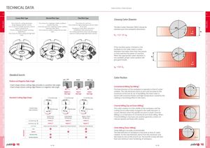
MILLINGOverviewFace millingHifeed millingShoulder millingProfile millingHardmillCenter & ChamferSpot faceEnd MillsSpare partsTechnical Data Work Material MILLINGOverviewFace millingHifeed millingShoulder millingProfile millingHardmillCenter & ChamferSpot faceEnd MillsSpare partsTechnical Data technical data Dados técnicos | Datos técnicos A A Coarse Pitch Type Normal Pitch Type Fine Pitch Type Choosing Cutter Diameter First choice for cutting aluminium First choice for roughing in stable conditions. First choice for cast iron. (long-chipping material - ISO N). Good productivity. First choice for high productivity with low width First choice for unstable operations due to Good chip space for roughing in steels, stainless of cut (Ae). The Best Cutter Diameter (ØDc) should belowest cutting forces.steel and super alloys.Roughing in super alloys materials inSmoth cutting allows longer overhangFirst choice for shallow cutting with low feedcombination with round inserts.selected upon the workpiece dimensionsøDc applications. rates. For cutting operations where chip dischange F ae First choice for deep cutting and high feedrates. volume is small and high table feed is desired. Dc = 1,3 - 1,5 ae If the machine power is limited or the workpiece is too wide, select a cutter diameter that takes more than two passes or that matches the power of machine. øDc When the appropriate cutter diameter isnot available, proper cutter position willae give good results. F ae = 3/4 Dc Standard inserts Cutter Position Positive and Negative Rake Angle - Insert shape whose cutting edge precedes is a positive rake angle. - Insert shape whose cutting edge follows is a negative rake angle. Conventional Milling (Up Milling) The feed direction of the workpiece is opposite to that of cutter Negative (-) Neutral Positive rotation. The chip thickness starts at zero and increases to the Rake Angle Rake Angle Rake Angle maximum at the end of cut. In Up Milling, the insert wear is severe with excessive friction and high temperature caused by the Standard Cutting Edge Shape (+) Axial Rake Angle (-) Axial Rake Angle (+) Axial Rake Angle rubbing or burnishing effect in the insert. Channel Milling (Up and Down Milling) Standard CuttingEdge Combinations Radial Rake Angle Radial Rake Angle Radial Rake Angle The cutter position is in the middle of the workpiece and thecutting force is alternately changed in the radial direction. It (+) (-) (-) causes vibration when the spindle structure is weak. Channel Milling is a combination of conventional and climb milling. When Double Positive Double Negative Negative / Positive Channel Milling is necessary use positive geometry cutters at (DP Edge Type) (DN Edge Type) (NP Edge Type) reduced speeds and feeds with coolant. Axial Rake Angle p Positive (+) Negative (-) Positive (+) Radial Rake Angle f Positive (+) Negative (-) Negative (-) Insert Used Positive Insert (One Sided Use) Negative Insert (Double Sided Use) Positive Insert (One Sided Use) Steel -Cast Iron- Climb Milling (Down Milling)Climb Milling is normally recommended.The feed direction of workpiece is the same as that of cutter Aluminium Alloy - - rotation. So the chip thickness starts from the maximum and Hardened Materials - decreases to zero at the end of cut. The tool life is long with less heat and minimum work hardening of workpiece. A - 254 A - 255