Каталог оснастка Dormer Pramet 2016 - страница 264
Навигация
 Общий каталог Dormer Pramet 2018
 Каталог Dormer Pramet токарная обработка 2021 - 2022
 Брошюра Dormer Pramet новинки 2021
 Каталог Dormer Pramet обработка резьбы 2021 - 2022
 Каталог Dormer Pramet фрезерование 2021 - 2022
- DIN 69871
- 69871-CC-OZ
- 69871-CC-ER
- 69871-CC-ER
- 69871-CC-ER
- 69871-CCM-ER
- 69871-CC-HKS
- 69871-W
- 69871-W
- 69871-W
- 69871-W-C
- 69871-W-C
- 69871-MT
- 69871-MTS
- 69871-RED-ISO
- 69871-FMH2
- 69871-FMH2
- 69871-FMH1
- 69871-FMH1
- 69871-FMH4
- 69871-DC
- 69871-QTCC
- 69871-QTCW
- 69871-HC
- 69871-HC
- 69871-SC
- 69871-SC
- 69871-SC
- 69871-SC
- 69871-SC-C
- 69871-IHA
- 69871-BLANKS
- 69871-TA
- ISO 60
- ISO-60-FMH1
- ISO-60-MT
- ISO-60-MTS
- ISO-60-RED-ISO
- MAS 403 BT
- BT-CC-OZ
- BT-CC-ER
- BT-CC-ER
- BT-CC-ER
- BT-CCM-ER
- BT-CC-HKS
- BT-W
- BT-W
- BT-W
- BT-W-C
- BT-W-C
- BT-MT
- BT-MTS
- BT-RED-ISO
- BT-FMH2
- BT-FMH2
- BT-FMH1
- BT-FMH1
- BT-FMH4
- BT-DC
- BT-QTCC
- BT-QTCW
- BT-HC
- BT-HC
- BT-SC
- BT-SC
- BT-SC
- BT-SC-C
- BT-IHA
- Bez názvu
- BT-TA
- DIN 2080
- 2080-CC-OZ
- 2080-CC-ER
- 2080-W
- 2080-W
- 2080-MT
- 2080-MTS
- 2080-RED-ISO
- 2080-FMH2
- 2080-FMH1
- 2080-DC
- 2080-QTCC
- 2080-BLANKS
- HSK-A
- HSK-A-CC-OZ
- HSK-A-CC-ER
- HSK-A-CCM-ER
- HSK-A-CC-HKS
- HSK-A-W
- HSK-A-W
- HSK-A-W-C
- HSK-A-FMH2
- HSK-A-FMH1
- HSK-A-FMH1
- HSK-A-FMH4
- HSK-A-MT
- HSK-A-MTS
- HSK-A-QTCC
- HSK-A-QTCW
- HSK-A-DC
- HSK-A-HC
- HSK-A-HC
- HSK-A-HC
- HSK-A-SC
- HSK-A-SC
- HSK-A-SC
- HSK-A-SC
- HSK-A-SC-C
- HSK-A-SC-C
- HSK-A-IHA
- HSK-A-BLANKS
- HSK-A-TA
- VDI
- VDI-B1
- VDI-B2
- VDI-B3
- VDI-B4
- VDI-B5
- VDI-B6
- VDI-B7
- VDI-B8
- VDI-C1
- VDI-C2
- VDI-C3
- VDI-C4
- VDI-D1
- VDI-D2
- VDI-AR
- VDI-AL
- VDI-E1
- VDI-E2
- VDI-E3
- VDI-E4
- VDI-F1
- VDI-HC
- VDI-Z2-S
- VDI-Z2-P
- VDI-DC
- VDI-DC-C
- VDI-QTCC
- VDI-QTCW
- VDI-A1
- VDI-A2
- VDI-TA
- MORSE
- MORSE-CC-ER
- MORSE-FMH2
- MORSE-QTCC
- MORSE-RED-MT
- MORSE-DC
- ADAPTORS / ADAPTÉRY ПЕРЕХОДНИК / 转接套
- AC-CC-ER
- ACF-CC-ER
- ACF-CC-ER-HX
- ACF-CCM-ER
- ACF-CCM-ER
- ACF-CCM-ER-D
- AC-HC
- AC-SC
- AW-DC
- AW-QTCC
- AW-QTCW
- AW-RED-W
- ACCESSORIES / PŘÍSLUŠENSTVÍ АКСЕССУАРЫ / 附件
- PS-69872
- PS-7388
- PS-BT
- PS-BT-C-S
- PS-2080-C
- OZ-C
- OZ-C-P
- OZ-C-SET-WP
- OZ-C-SET-WB
- OZ-C-SET-P-WP
- OZ-C-SET-P-WB
- ER-C
- ER-C-P
- ER-C-S
- ER-C-SC4
- ER-T
- ER-T-SC4
- ER-C-SET-WP
- ER-C-SET-WB
- ER-C-SET-P-WP
- ER-C-SET-P-WB
- ER-C-SET-S-WP
- ER-C-SET-S-WB
- ER-C-SET-SC4-WP
- ER-C-SET-SC4-WB
- ER-T-SET-WP
- ER-T-SET-WB
- ER-T-SET-SC4-WP
- ER-T-SET-SC4-WB
- HC-C
- HC-C-S
- QTCW-1
- QTCW-2
- QTCW-3
- QTCC-1
- QTCC-2
- QTCC-3
- QTCR
- HKS-C
- HKS-C-S
- N-OZ
- N-OZ-SR
- SR-OZ
- N-ER-M
- N-ER
- N-ER-SR
- N-ER-SR-SN
- SR-ER
- K-HKS
- K-OZ
- K-ER
- K-ER-M
- K-FMH
- E-MORSE
- E-HKS
- S-FMH
- S-FMH-C
- S-W
- F-FMH2
- DR-FMH2
- DS-FMH4
- S-DS-FMH4
- CT-HSK-A
- K-CT-HSK-A
- VDI-RS-E2
- VDI-SHIMS
- VDI-NOZZ
- TW
- AB-A360
- AB-S90
- TECHNICAL PART
- Steep Taper
- Pull studs
- HSK (hollow taper shanks)
- HSK coolant tubes
- Effects of imbalance on machine spindles, toolholders and tools
- Hydraulic expansion chucks
- Operating and user instructions for hydraulic expansion chucks
- Torques for clamping end-mills in end mill holders DIN 6359
- Operating and user instructions for CNC-drill chucks
- Mounting instructions for ER-Collets per DIN STD 6499
- Mounting instruction for sealing discs
- Quick-change tapping chucks
- Instructions for tapping chucks
- Screw taps-shaft size
- Tool assignment for disc turrets
- High-performance milling chucks HKS-system
- Product codes description
- TECHNICKÁ ČÁST
- STRMÝ KUŽEL
- TAŽNÉ ČEPY
- HSK (duté kuželové stopky)
- TRUBICE PRO ŘEZNOU KAPALINU HSK
- ÚČINKY NEROVNOVÁHY NA VŘETENA, DRŽÁKY A NÁSTROJE
- ÚČINKY NEROVNOVÁHY NA VŘETENA, DRŽÁKY A NÁSTROJE
- HYDROUPÍNAČE
- NÁVOD K OBSLUZE PRO HYDROUPÍNAČE
- UTAHOVACÍ MOMENTY ŠROUBŮ PRO UPNUTÍ STOPKOVÝCH FRÉZ V DRŽÁCÍCH DIN 6359
- NÁVOD K OBSLUZE PRO NC VRTACÍ HLAVIČKY
- NÁVOD K MONTÁŽI PRO KLEŠTINOVÉ UPÍNAČE ER PODLE DIN STD 6499
- NÁVOD K MONTÁŽI PRO TĚSNICÍ KROUŽKY
- RYCHLOVÝMĚNNÉ KLEŠTINOVÉ UPÍNAČE PRO ZÁVITOVÁNÍ
- NÁVOD PRO RYCHLOVÝMĚNNÉ ZÁVITOVACÍ UPÍNAČE
- TABULKA ČTYŘHRANŮ STOPEK ZÁVITNÍKŮ
- ZNAČENÍ A ORIENTACE DRŽÁKŮ VDI V REVOLVEROVÝCH HLAVÁCH
- SYSTÉM HKS SE SILOVÝMI UPÍNACÍMI POUZDRY
- POPISY KÓDŮ VÝROBKŮ
- ТЕХНИЧЕСКАЯ ЧАСТЬ
- КОНУС SK
- ШТРЕВЕЛИ
- КОНУС HSK (от англ. hollow taper shanks – полый конус)
- КОНУС HSK (от англ. hollow taper shanks – полый конус)
- Патрубки для подачи СОЖ к оправкам HSK
- ЭФФЕКТ ДИСБАЛАНСА ШПИНДЕЛЯ СТАНКА,ОПРАВОК И РЕЖУЩЕГО ИНСТРУМЕНТА
- ЭФФЕКТ ДИСБАЛАНСА ШПИНДЕЛЯ СТАНКА,ОПРАВОК И РЕЖУЩЕГО ИНСТРУМЕНТА
- ГИДРАВЛИЧЕСКИЕ ПАТРОНЫ
- ИНСТРУКЦИЯ ПО ЭКСПЛУАТАЦИИ ГИДРАВЛИЧЕСКИХ ПАТРОНОВ
- МОМЕНТЫ ЗАТЯЖКИ КОНЦЕВЫХ ФРЕЗ В ОПРАВКАХ ПО DIN 6359
- Инструкции по эксплуатации сверлильных патронов для станков с ЧПУ
- ИНСТРУКЦИИ ПО УСТАНОВКЕ ЦАНГ ER ПО DIN STD 6499
- ИНСТРУКЦИЯ ПО УСТАНОВКЕ УПЛОТНИТЕЛЬНЫХ КОЛЕЦ
- БЫСТРОСМЕННЫЕ РЕЗЬБОНАРЕЗНЫЕ ПАТРОНЫ
- ИНСТРУКЦИЯ ДЛЯ РЕЗЬБОНАРЕЗНЫХ ПАТРОНОВ
- СООТВЕТСТВИЕ РАЗМЕРА РЕЗЬБЫ И РАЗМЕРА ХВОСТОВИКА МЕТЧИКА
- ПРИМЕНЕНИЕ ИНСТРУМЕНТА В ДИСКОВОЙ РЕВОЛЬВЕРНОЙ ГОЛОВКЕ
- ВЫСОКОПРОИЗВОДИТЕЛЬНЫЕ ФРЕЗЕНЫЕ ОПРАВКИ СИСТЕМЫ HKS
- СИСТЕМА ОБОЗНАЧЕНИЯ
- 技术部分
- 锥柄
- 拉钉
- HSK(中空锥形柄)
- HSK冷却液管
- 不平衡对机床主轴、刀架和刀具的影响
- 不平衡对机床主轴、刀架和刀具的影响
- 液压刀柄
- 液压刀柄操作和使用说明
- 侧固刀柄(DIN 6359)端面铣刀夹紧扭矩
- CNC钻卡头操作和使用说明
- ER夹头安装说明,依照DIN STD 6499
- 密封圈安装说明
- 快速更换式攻丝卡盘
- 攻丝卡盘说明
- 攻丝-轴尺寸
- 盘塔刀具分配
- 强力刀柄HKS系统
- 产品代码描述
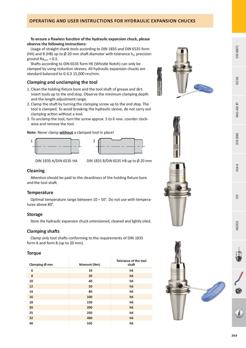
OPERATING AND USER INSTRUCTIONS FOR HYDRAULIC EXPANSION CHUCKS
To ensure a flawless function of the hydraulic expansion chuck, please
observe the following instructions:
Usage of straight shank tools according to DIN 1835 and DIN 6535 form
(HA) and B (HB) up to Ø 20 mm shaft diameter with tolerance h , precision
6 ground Ra = 0.3. min
Shafts according to DIN 6535 form HE (Whistle Notch) can only be
clamped by using reduction sleeves. All hydraulic expansion chucks are
standard balanced to G 6.3 15,000 rev/min.
Clamping and unclamping the tool
1. Clean the holding fixture bore and the tool shaft of grease and dirt.
Insert tools up to the end stop. Observe the minimum clamping depth
and the length adjustment range.
2. Clamp the shaft by turning the clamping screw up to the end stop. The
tool is clamped. To avoid breaking the hydraulic sleeve, do not carry out
clamping action without a tool.
3. To unclamp the tool, turn the screw approx. 5 to 6 revs. counter clock-
wise and remove the tool.
Note: Never clamp without a clamped tool in place!
1 2
DIN 1835 A/DIN 6535 HA DIN 1835 B/DIN 6535 HB up to Ø 20 mm
Cleaning
Attention should be paid to the cleanliness of the holding fixture bore
and the tool shaft.
Temperature
Optimal temperature range between 10 – 50°. Do not use with tempera-
tures above 80°.
Storage
Store the hydraulic expansion chuck untensioned, cleaned and lightly oiled.
Clamping shafts
Clamp only tool shafts conforming to the requirements of DIN 1835
form A and form B (up to 20 mm).
Torque
| Clamping-Ø mm | Moment (Nm) | Tolerance of the tool shaft |
| 6 | 10 | h6 |
| 8 | 20 | h6 |
| 10 | 40 | h6 |
| 12 | 50 | h6 |
| 14 | 80 | h6 |
| 16 | 100 | h6 |
| 18 | 150 | h6 |
| 20 | 200 | h6 |
| 25 | 250 | h6 |
| 32 | 400 | h6 |
| 40 | 550 | h6 |