Техническая информация Sumitomo - страница 9
Навигация
 Каталог Sumitomo пластины с алмазными вставками Sumidia
 Общий каталог Sumitomo 2019 - 2020
 Каталог Sumitomo токарные резцы (державки) для наружного точения
 Каталог Sumitomo твердосплавные пластины
 Каталог Sumitomo фрезы со сменными пластинами
 Каталог Sumitomo пластины с режущей кромкой-моноалмаз Sumicristal
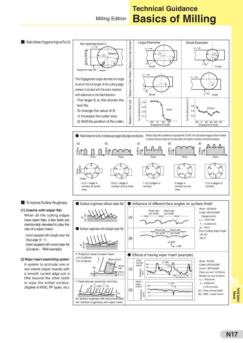
Technical Guidance Milling Edition Basics of Milling ■ Relation Between Engagement Angle and Tool Life Work material feed direction Vf Relation to Cutter Diameter Large Diameter Small Diameter Cutting Width W f f DC Rotation DC DC E E Small Large Engagement angle E Insert Relation to Cutter Position f The Engagement angle denotes the angle f at which the full length of the cutting edge comes in contact with the work material, E with reference to the feed direction. Small E Large · The larger E is, the shorter the Relation to Tool Life Tool Life (Milling Area) (m2) 0.4 Tool Life (Milling Area) (m2) tool life. 0.3 0.6 · To change the value of E: S50C FC250 0.2 0.4 1) Increase the cutter size. 0.1 0.2 2) Shift the position of the cutter. -30° 0° 30° 60° -20° 0° 20° 40° 60° 80° Engagement Angle Engagement Angle ● Relation between the number of simultaneously engaged cutting edges and cutting force: Normally, cutting width is considered to be appropriate with 70 to 80% of the cutter diameter engaged as shown in example d). However, this may not apply due to the actual rigidity of the machine or work piece, and machine horsepower. a) b) c) d) e) Cutting force Cutting force Cutting force Cutting force Cutting force Time Time Time Time Time Wor k material Cutter · 0 or 1 edge in · Only 1 edge in · 1 or 2 edges in · 2 edge in · 2 to 3 edges in contact at same contact at any time. contact. contact at any contact. time. time. ■ To Improve Surface Roughness ● Surface roughness without wiper flat ● Influence of different face angles on surface finish (1) Inserts with wiper flat Feed rate Feed rate · Work : SCM435 per tooth per tooth · Cutter: DPG5160R When all the cutting edges HC (A) (Single tooth) have wiper flats, a few teeth are · vc = 154m/min intentionally elevated to play the fz = 0.234mm/t role of a wiper insert. ● Surface roughness with straight wiper flat ap = 2mm Feed rate Feed rate · Face Cutting Edge Angle · Insert equipped with straight wiper flat per tooth per tooth (A): 28' (Face angle: 15' - 1°) (B) (B): 6' · Insert equipped with curved wiper flat ×2,000 HF ×100 (Curvature ≈ R500 (example)) h: Projection value of wiper insert ● Effects of having wiper insert (example) (2) Wiper insert assembling system ( Fc: 0.05mm ) Wiper insert (Only Al: 0.03mm · Work : FC250 normal ×1,000 A system to protrude one or Normal teeth) 20 20 · Cutter: DPG4100R two inserts (wiper inserts) with HW teeth (C) Roughness 15 · Insert : SPCH42R (µm) 10 · Face run-out : 0.015mm a smooth curved edge just a h 5 · Radial run-out: 0.04mm little beyond the other teeth Feed rate per rev. N f : Feed rate per revolution (mm/rev) (With 1 · vc = 105m/min to wipe the milled surface. wiper ×1,000 fz = 0.29mm/t (Applies to WGC, RF types, etc.) insert) 20 20 (1.45 mm/rev) (D) Roughness 15 (C) : Only normal teeth Technical Guidance / HC (µm) 10 (D) : With 1 wiper insert References HW 5 Hc: Surface roughness with only normal teeth Hw: Surface roughness with wiper insert N17