Техническая информация Sumitomo - страница 11
Навигация
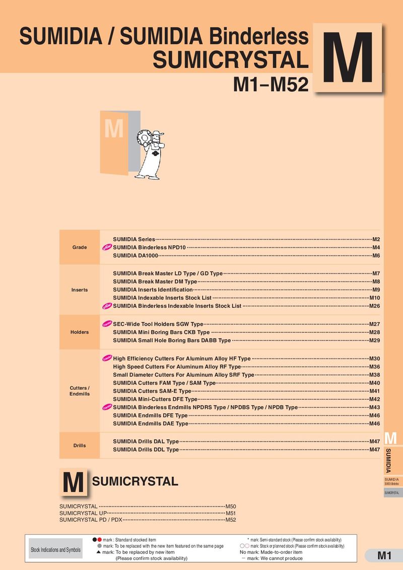 Каталог Sumitomo пластины с алмазными вставками Sumidia
 Общий каталог Sumitomo 2019 - 2020
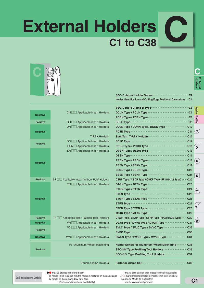 Каталог Sumitomo токарные резцы (державки) для наружного точения
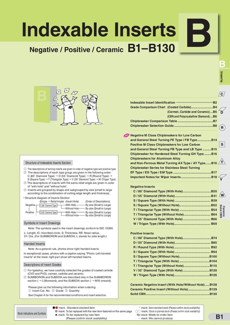 Каталог Sumitomo твердосплавные пластины
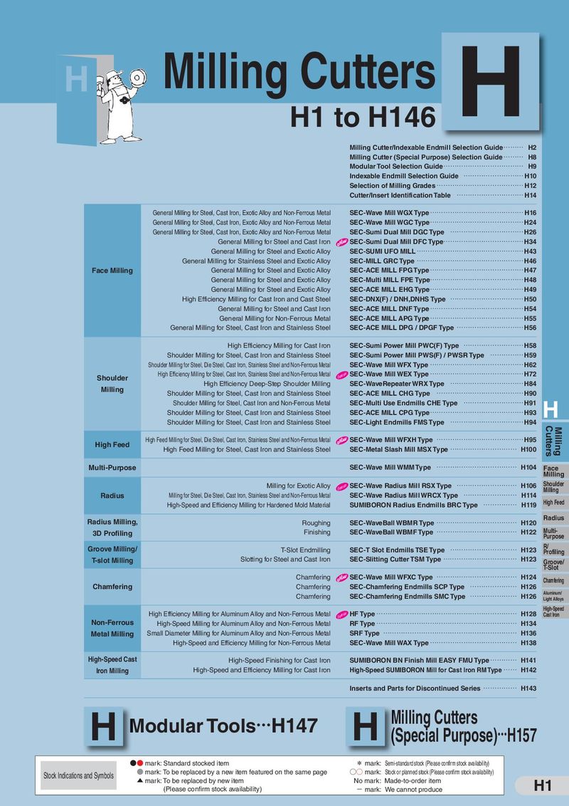 Каталог Sumitomo фрезы со сменными пластинами
 Каталог Sumitomo пластины с режущей кромкой-моноалмаз Sumicristal
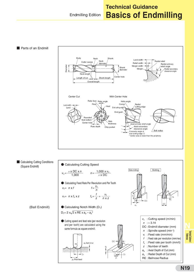
Technical Guidance Endmilling Edition Basics of Endmilling ■ Parts of an Endmill Body Neck Shank Land width Cutter sweep Neck Radial relief diameter Relief width Radial primary Diameter Shank Margin width relief angle diameter Margin Radial secondary clearance angle Neck length Length of cut Shank length Center hole Overall length Center Cut With Center Hole Rake face Rake angle Helix angle Land width Flute Corner Radial Land Heel End cutting edge cutting edge End gash Rounded flute bottom Web Center hole thickness Axial primary relief angle Flute depth Chip pocket Axial secondary clearance angle Concavity angle of Ball radius end cutting edge (*) * Center area is lower than the periphery ■ Calculating Cutting Conditions ● Calculating Cutting Speed (Square Endmill) π x DC x n 1,000 x vc Side milling Slotting vc = 1,000 n= π x DC ● Calculating Feed Rate Per Revolution and Per Tooth vf = nxf f= vf n vf = n x fz x z fz = f = vf ap z nxz ap DC ae DC (Ball Endmill) ● Calculating Notch Width (D1) D1= 2 x 2 x RE x ap – ap2 ● Cutting speed and feed rate (per revolution vc : Cutting speed (m/min) and per tooth) are calculated using the π : ≈ 3.14 N same formula as square endmill. DC : Endmill diameter (mm) n : Spindle speed (min-1) Technical Guidance / vf : Feed rate (mm/min) References f : Feed rate per revolution (mm/rev) ap Depth of cut DC fz : Feed rate per tooth (mm/t) RE RE ap z : Number of teeth ap : Axial Depth of Cut (mm) D1 D1 ae : Radial Depth of Cut (mm) pf Pick feed pf RE : Ballnose Radius N19