Техническая информация Sumitomo - страница 19
Навигация
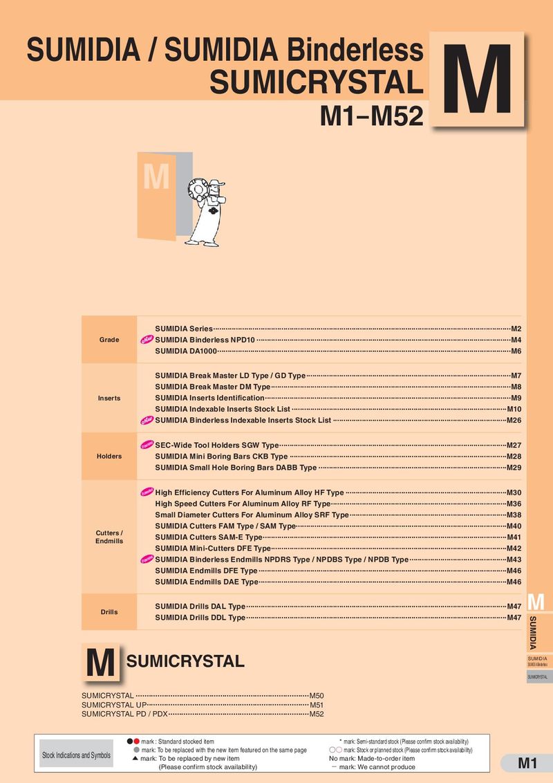 Каталог Sumitomo пластины с алмазными вставками Sumidia
 Общий каталог Sumitomo 2019 - 2020
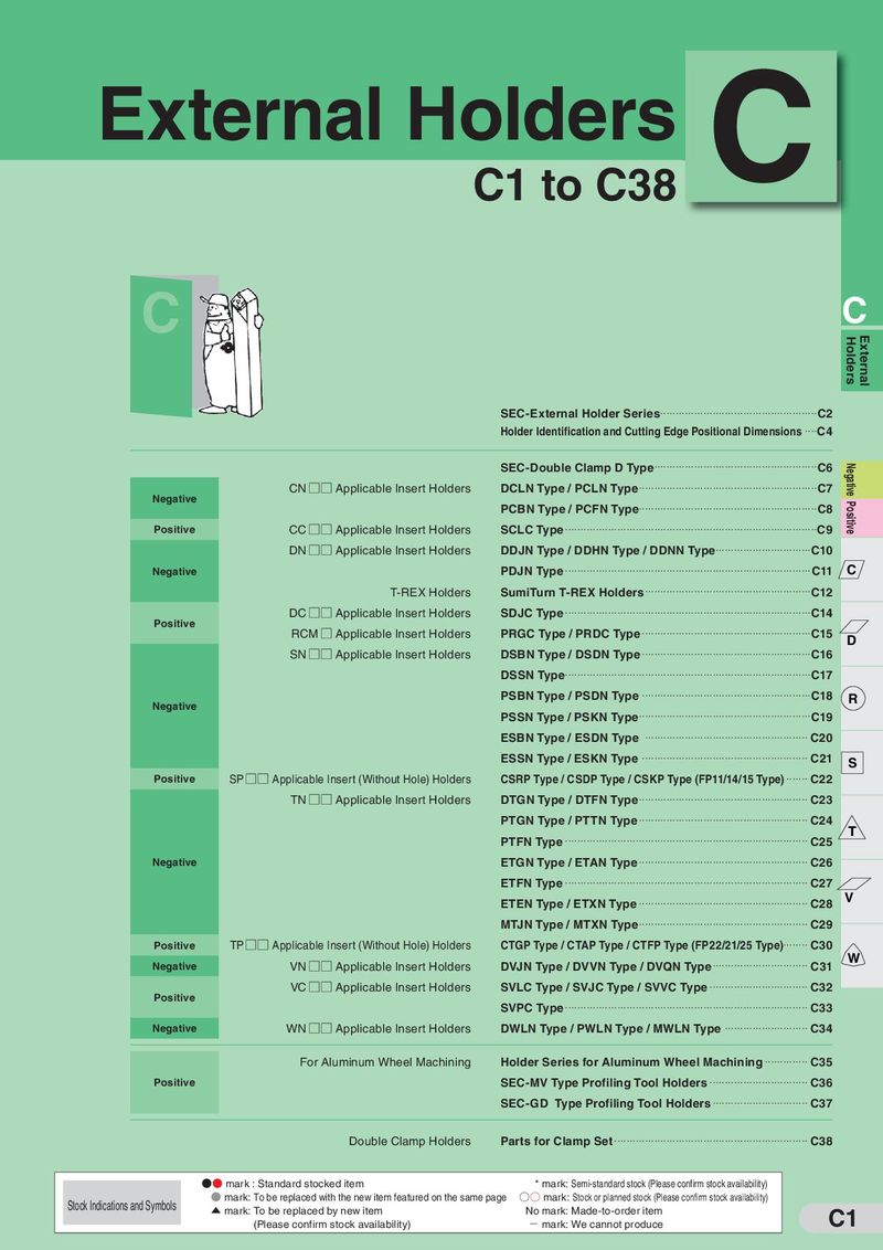 Каталог Sumitomo токарные резцы (державки) для наружного точения
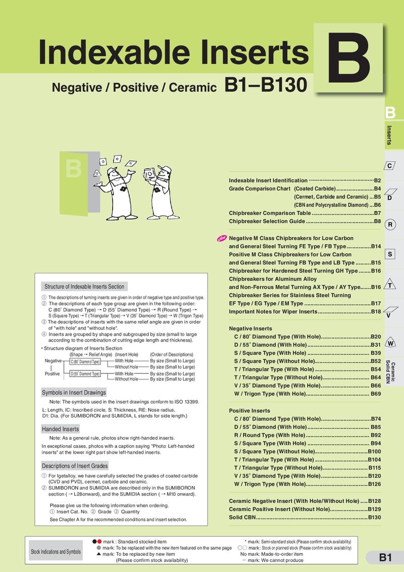 Каталог Sumitomo твердосплавные пластины
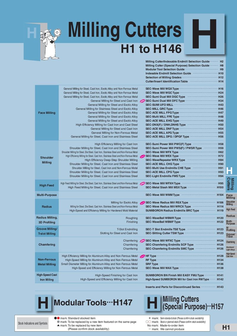 Каталог Sumitomo фрезы со сменными пластинами
 Каталог Sumitomo пластины с режущей кромкой-моноалмаз Sumicristal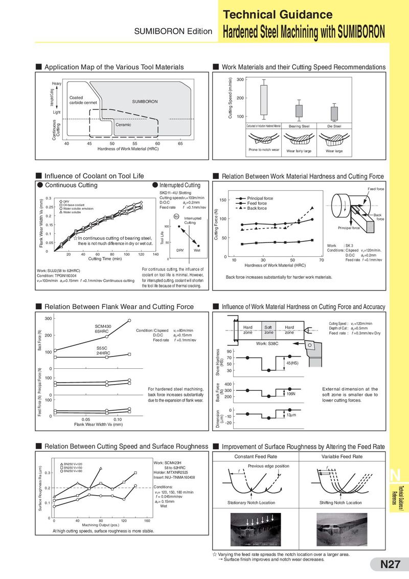
Hardened Steel Machining with SUMIBORON
- Application Map of the Various Tool Materials
- Work Materials and their Cutting Speed Recommendations
300 Heavy
Coated 200 carbide cermet SUMIBORON Light 100
Ceramic Carburised or Induction Hardened Material Bearing Steel Die Steel
40 45 50 55 60 65
Hardness of Work Material (HRC) Prone to notch wear Wear fairly large Wear large
- Influence of Coolant on Tool Life
- Relation Between Work Material Hardness and Cutting Force
- Continuous Cutting
- Interrupted Cutting
Feed force SKD11–4U Slotting
| 0.3 | Cutting speed v =100m/min | Principal force | ||
| c | 150 | |||
| DRY | D.O.C | a =0.2mm | Feed force | |
| Oil-base coolant | p | |||
| 0.25 | Feed rate | f =0.1mm/rev | Back force | |
| Water soluble emulsion | ||||
| Water soluble |
0.2 Heavy Back
Interrupted 100 force
Cutting 0.15 100 Principal force 0.1 ☆
In continuous cutting of bearing steel, 50
| 0.05 | there is not much difference in dry or wet cut. | 50 | |
| Work : SK 3 |
0 DRY Wet Conditions : C/speed vc =120m/min.
| 20 | 40 | 60 | 80 | 100 | 120 | 140 | 0 | D.O.C | a =0.2mm | |
| Cutting Time (min) | p |
0 10 30 50 70 Feed rate f =0.1mm/rev
Hardness of Work Material (HRC) For continuous cutting, the influence of Work: SUJ2(58 to 62HRC) Condition: TPGN160304 coolant on tool life is minimal. However,
Back force increases substantially for harder work materials. v =100m/min a =0.15mm f =0.1mm/rev Continuous cutting for interrupted cutting, coolant will shorten c p the tool life because of thermal cracking.
- Relation Between Flank Wear and Cutting Force
- Influence of Work Material Hardness on Cutting Force and Accuracy
300 Cutting Speed : v =120m/min SCM430 c
Hard Soft Hard Depth of Cut : a =0.5mm
65HRC Condition: C/speed v =80m/min p
c zone zone zone Feed rate : f = 0.3mm/rev Dry
| 200 | D.O.C | ap=0.15mm | ||
| Feed rate f =0.1mm/rev | ||||
| Work: S38C | ||||
| S55C |
100 24HRC 90
70 50 45(HS) 0 30 100
400
| For hardened steel machining, | 300 | External dimension at the | ||
| 0 | back force increases substantially | 106N | soft zone is smaller due to | |
| 200 | ||||
| 100 | due to the expansion of flank wear. | lower cutting forces. | ||
| 0 | ||||
| 0 | -10 | 13μm |
0.05 0.10 Flank Wear Width V (mm) -20 B
- Relation Between Cutting Speed and Surface Roughness
- Improvement of Surface Roughness by Altering the Feed Rate
Constant Feed Rate Variable Feed Rate Work: SCM420H BN250 V=120 Previous edge position
BN250 V=150 58 to 62HRC N
BN250 V=180 Holder: MTXNR2525 0.3 Insert: NU–TNMA160408 0.2 Conditions:
v = 120, 150, 180 m/min c f = 0.045mm/rev
| a = 0.15mm | Stationary Notch Location | Shifting Notch Location | ||
| 0.1 | p | |||
| Wet | ||||
| 0 |
0 40 80 120 160
Machining Output (pcs.) At high cutting speeds, surface roughness is more stable.
☆ Varying the feed rate spreads the notch location over a larger area. → Surface finish improves and notch wear decreases. N27