Техническая информация Sumitomo - страница 7
Навигация
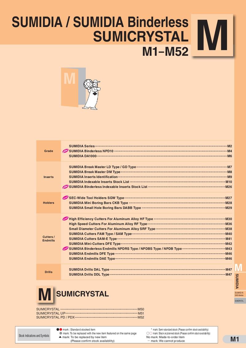 Каталог Sumitomo пластины с алмазными вставками Sumidia
 Общий каталог Sumitomo 2019 - 2020
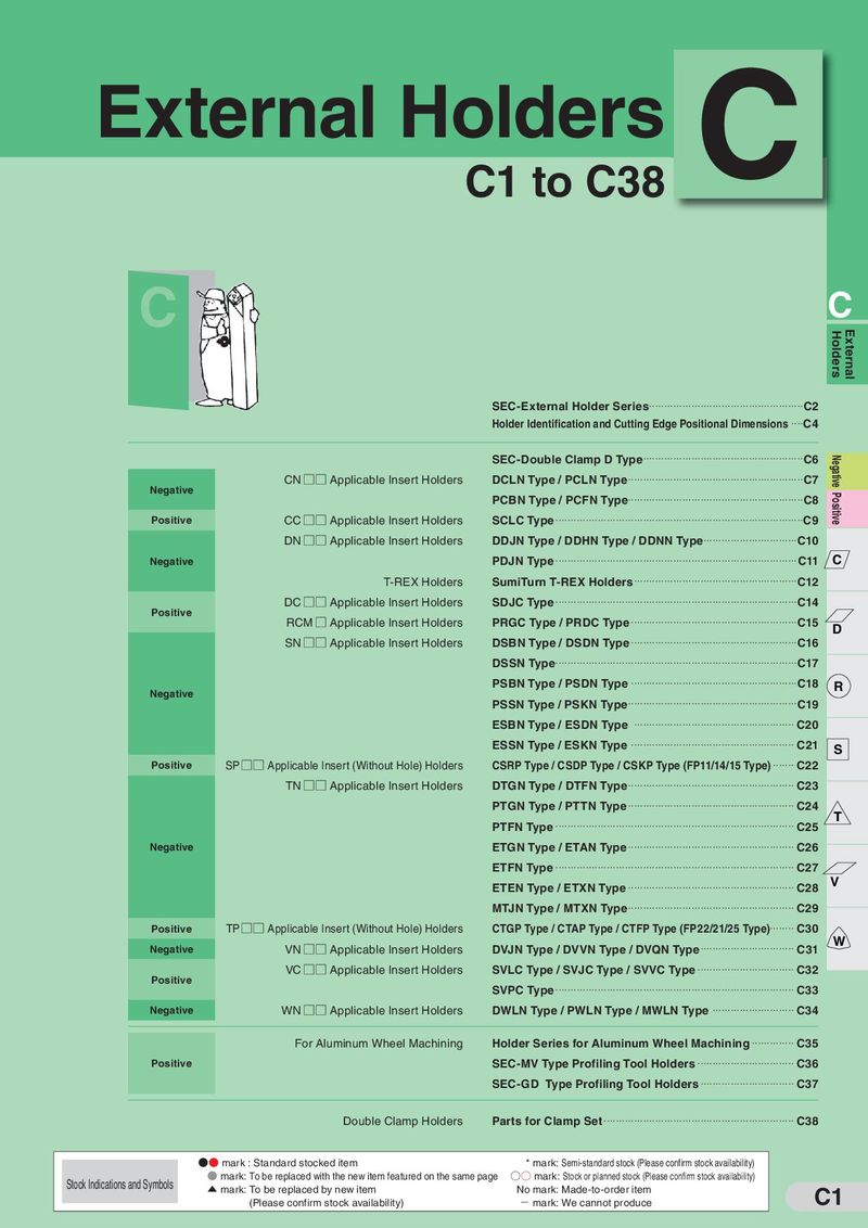 Каталог Sumitomo токарные резцы (державки) для наружного точения
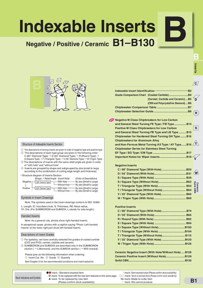 Каталог Sumitomo твердосплавные пластины
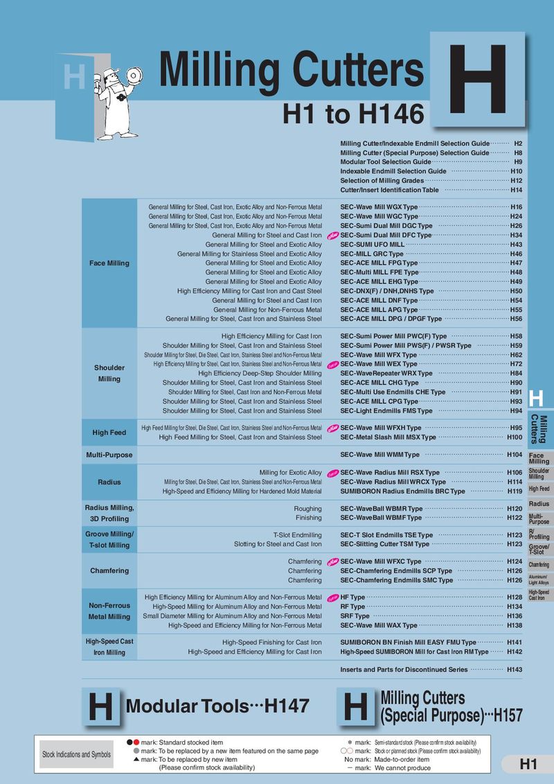 Каталог Sumitomo фрезы со сменными пластинами
 Каталог Sumitomo пластины с режущей кромкой-моноалмаз Sumicristal
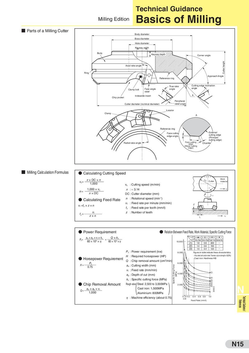
Technical Guidance Milling Edition Basics of Milling ■ Parts of a Milling Cutter Body diameter Boss diameter Hole diameter Keyway width Body Keyway depth Corner angle Axial rake angle Cutter height Ring Approach Angle Reference ring True rake Cutting edge inclination Clamp bolt Face angle angle angle relief Indexable insert A Chip pocket Peripheral Cutter diameter (nominal diameter) relief angle Locator Clamp A Reference ring Face cutting External edge angle cutting edge (Principal cutting edge) Radial rake angle Face cutting Chamfer edge (Wiper cutting edge) ■ Milling Calculation Formulas ● Calculating Cutting Speed π × DC × n DC Work vc= Cutter material 1,000 vc : Cutting speed (m/min) 1,000 × vc π : ≈ 3.14 n vf n= π × DC DC : Cutter diameter (mm) n ● Calculating Feed Rate n : Rotational speed (min-1) vf =fz × z × n vf : Feed rate per minute (mm/min) ap fz : Feed rate per tooth (mm/t) fz = vf z : Number of teeth z×n fz vf ● Power Requirement ● Relation Between Feed Rate, Work Material, Specific Cutting Force ae × ap × vf × kc Q × kc Symbol Pc= 60 × 106 × η = 60 × 103 × η Work Material Alloy Steel Carbon Steel Cast Iron Aluminium Aloy 10.000 No. (1) 1.8 0.8 200 Q (2) 1.4 0.6 160 Q (3) 1.0 0.4 120 Q Pc : Power requirement (kw) 8.000 Figures in table indicate these characteristics. H : Required horsepower (HP) · Alloy steel and carbon steel: Traverse rupture strengthσ B(GPa) ● Horsepower Requirement · Cast iron: Hardness HB Pc Q : Chip removal amount (cm3/min) H= 6.000 0.75 ae : Cutting width (mm) Specific Cutting Force vf : Feed rate (mm/min) (MPa) ap : Depth of cut (mm) 4.000 kc : Specific cutting force (MPa) ● Chip Removal Amount Rough ( ) value Steel: 2,500 to 3,000MPa 2.000 Q= ae × ap × vf Cast iron: 1,500MPa N 1,000 Aluminium: 800MPa η : Machine efficiency (about 0.75) 0 0.1 0.2 0.4 0.6 0.8 1.0 Technical Guidance / 0.04 Feed Rate (mm/t) References N15