Техническая информация Sumitomo - страница 10
Навигация
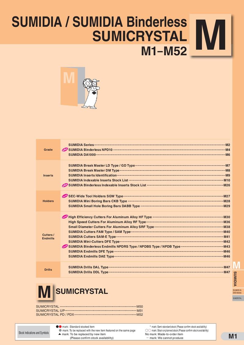 Каталог Sumitomo пластины с алмазными вставками Sumidia
 Общий каталог Sumitomo 2019 - 2020
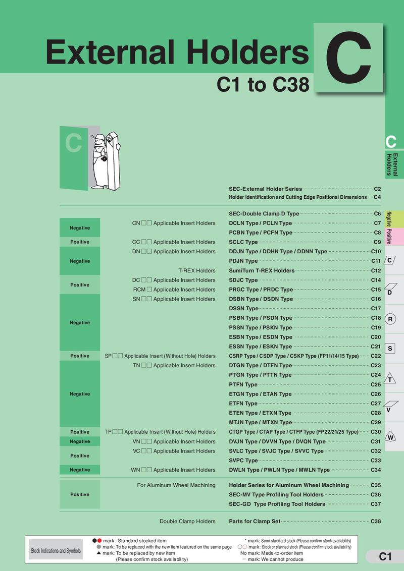 Каталог Sumitomo токарные резцы (державки) для наружного точения
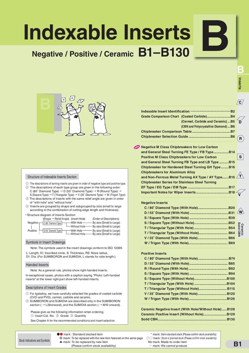 Каталог Sumitomo твердосплавные пластины
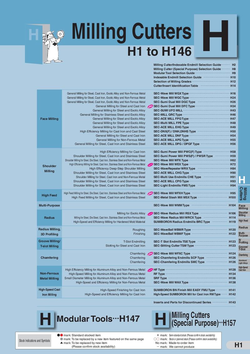 Каталог Sumitomo фрезы со сменными пластинами
 Каталог Sumitomo пластины с режущей кромкой-моноалмаз Sumicristal
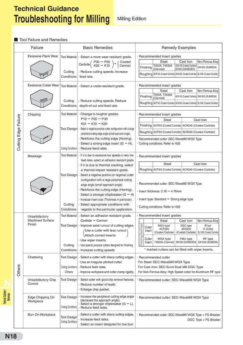
Technical Guidance Troubleshooting for Milling Milling Edition ■ Tool Failure and Remedies Failure Basic Remedies Remedy Examples Excessive Flank Wear Tool Material · Select a more wear resistant grade. ・Recommended insert grades P30 P20 Coated Steel Cast Iron Non-Ferrous Alloy ( ){ Carbide K20 K10 Cermet T250A, T4500A ACK100 (Coated Carbide) Finishing DA1000 (SUMIDIA) (Cermet) BN7000 (SUMIBORON) Cutting · Reduce cutting speeds. Increase Roughing ACP100 (Coated Carbide) ACK200 (Coated Carbide) DL1000 (Coated Carbide) Conditions feed rate. Excessive Crater Wear Tool Material · Select a crater-resistant grade. ・Recommended insert grades Steel Cast Iron Non-Ferrous Alloy Finishing T250A, T4500A ACK100 (Coated Carbide) DA1000 (SUMIDIA) Cutting · Reduce cutting speeds. Reduce (Cermet) Conditions depth-of-cut and feed rate. Roughing ACP100 (Coated Carbide) ACK200 (Coated Carbide) DL1000 (Coated Carbide) Cutting Edge Failure Chipping Tool Material · Change to tougher grades. ・Recommended insert grades P10 P20 P30 Steel Cast Iron K01 K10 K20 Finishing ACP200 (Coated Carbide) ACK200 (Coated Carbide) Tool Design · Select a negative-positive cutter configuration with a large peripheral cutting edge angle (small approach angle). Roughing ACP300 (Coated Carbide) ACK300 (Coated Carbide) · Reinforce the cutting edge (Honing). ・Recommended cutter: SEC-WaveMill WGX Type · Select a strong edge insert (G H). ・Cutting conditions: Refer to H20 Cutting Conditions · Reduce feed rates. Breakage Tool Material · If it is due to excessive low speeds or very low ・Recommended insert grades feed rates, select an adhesion resistant grade. · If it is due to thermal cracking, select Steel Cast Iron a thermal impact resistant grade. Roughing ACP300 (Coated Carbide) ACK300 (Coated Carbide) Tool Design · Select a negative-positive (or negative) cutter configuration with a large peripheral cutting edge angle (small approach angle). ・Recommended cutter: SEC-WaveMill WGX Type · Reinforce the cutting edge (Honing). ・Insert thickness: 3.18 4.76mm · Select a stronger chipbreaker (G H) · Increase insert size (Thickness in particular). ・Insert type: Standard Strong edge type Cutting · Select appropriate conditions with ・Cutting conditions: Refer to H20 Conditions regards to the particular application. Unsatisfactory Tool Material · Select an adhesion resistant grade. ・Recommended insert grades Machined Surface Carbide Cermet Steel Cast Iron Non-Ferrous Alloy Finish Tool Design · Improve axial runout of cutting edges. Finishing General Purpose WGX type* DGC type RF type* Cutter ACP200 ACK200 H1 (Carbide) ( ) Use a cutter with less runout Insert (Coated Carbide) (Coated Carbide) DL1000 (Coated Carbide) Attach correct inserts. · Use wiper inserts. Cutter WGX type FMU type RF type Insert T4500A (Cermet) BN7000 (SUMIBORON) DA1000 (SUMIDIA) Cutting · Use special purpose cutters designed for finishing. Conditions · Increase cutting speeds * marked cutters can be fitted with wiper inserts. Chattering Tool Design · Select a cutter with sharp cutting edges. ・Recommended cutter · Use an irregular pitched cutter. For Steel: SEC-WaveMill WGX Type Others Cutting Conditions · Reduce feed rates. For Cast Iron: SEC-Sumi Dual Mill DGC Type Others · Improve workpiece and cutter clamp rigidity. For Non-Ferrous Alloy: High Speed cutter for Aluminium RF type N Unsatisfactory Chip Tool Design · Select cutter with good chip removal features. ・Recommended cutter: SEC-WaveMill WGX Type Control · Reduce number of teeth. Technical Guidance / · Enlarge chip pocket. References Edge Chipping On Tool Design · Increase the peripheral cutting edge angle ・Recommended cutter: SEC-WaveMill WGX Type Workpiece (decrease the approach angle). · Select a stronger chipbreaker (G L). Cutting Conditions · Reduce feed rates. Burr On Workpiece Tool Design · Select a cutter with sharp cutting edges. ・Recommended cutter: SEC-WaveMill WGX Type + FG Breaker Cutting Conditions · Increase feed rates. DGC Type + FG Breaker · Select an insert designed for low burr. N18