Техническая информация Sumitomo - страница 8
Навигация
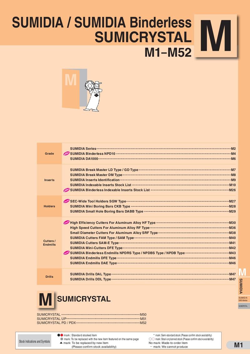 Каталог Sumitomo пластины с алмазными вставками Sumidia
 Общий каталог Sumitomo 2019 - 2020
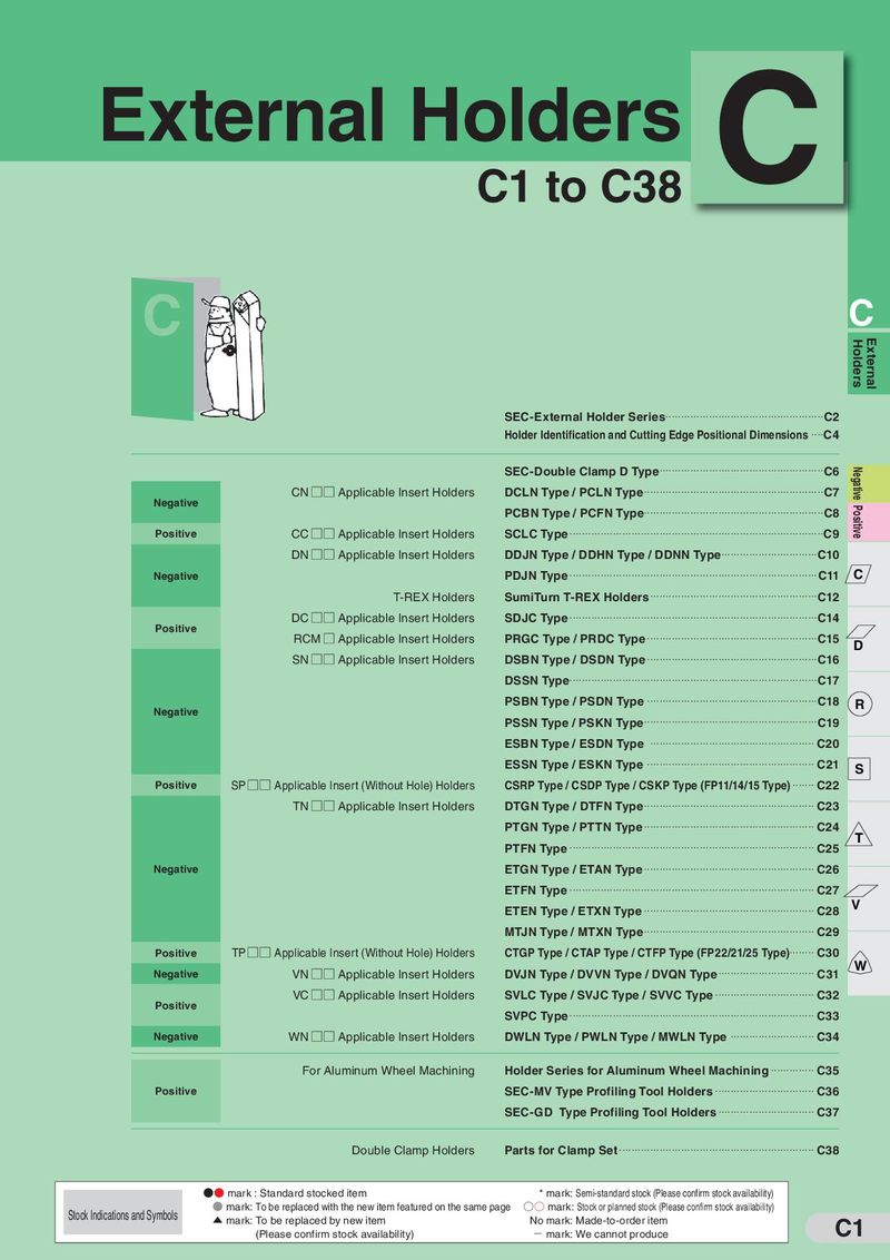 Каталог Sumitomo токарные резцы (державки) для наружного точения
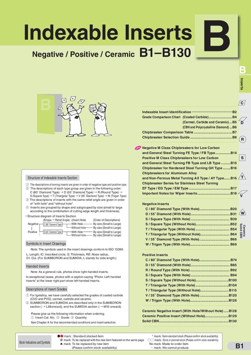 Каталог Sumitomo твердосплавные пластины
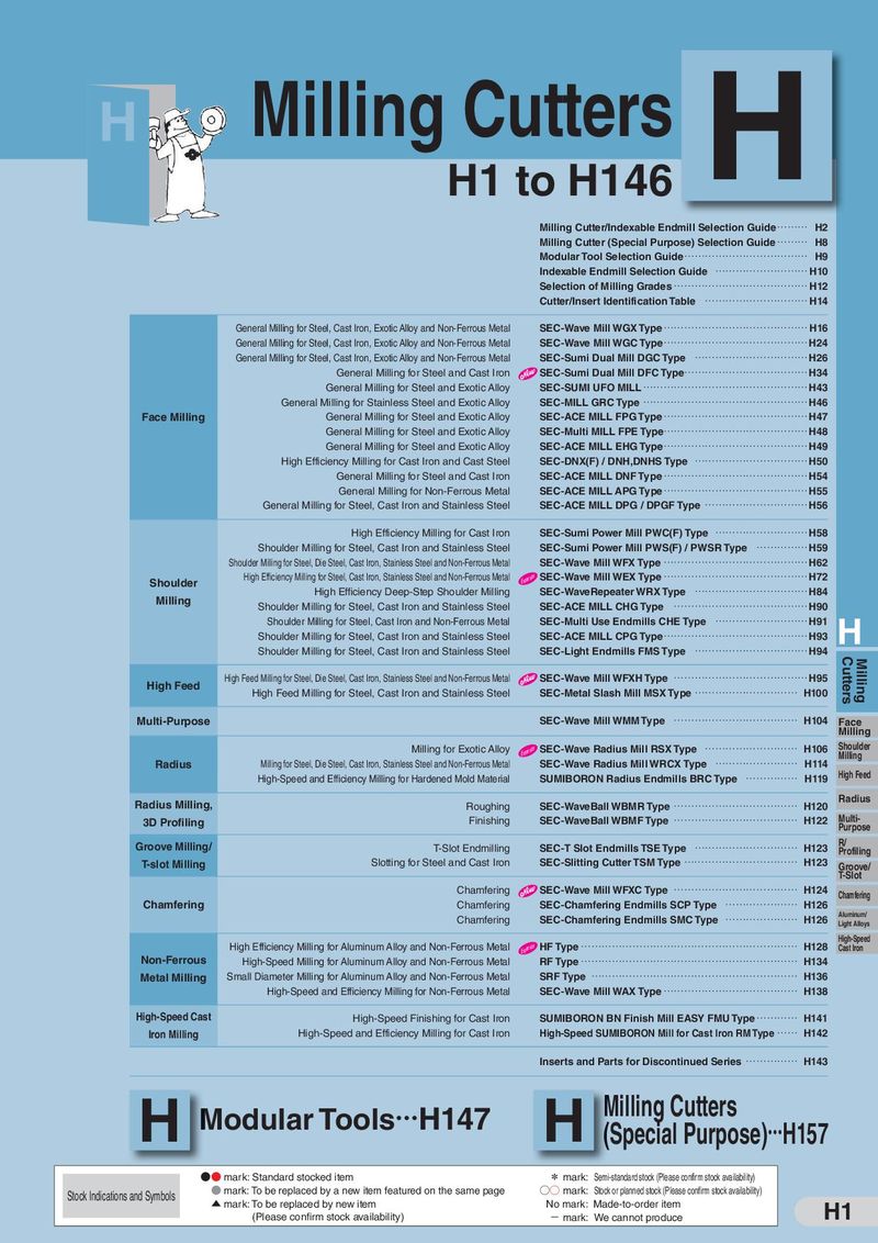 Каталог Sumitomo фрезы со сменными пластинами
 Каталог Sumitomo пластины с режущей кромкой-моноалмаз Sumicristal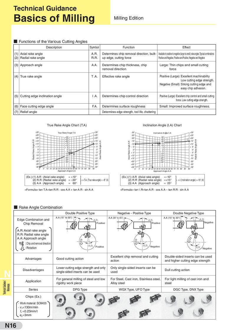
Technical Guidance
Basics of Milling Milling Edition
■ Functions of the Various Cutting Angles
Description Symbol Function Effect
(1) Axial rake angle A.R. Determines chip removal direction, built- Available in positive to negative (large to small) rake angles; Typical combinations:
(2) Radial rake angle R.R. up edge, cutting force Positive and Negative, Positive and Positive, Negative and Negative
(3) Approach angle A.A. Determines chip thickness, chip Large: Thin chips and small cutting
removal direction force
(4) True rake angle T.A. Effective rake angle Positive (Large): Excellent machinability
Low cutting edge strength.
Negative (Small): Strong cutting edge and
easy chip adhesion.
(5) Cutting edge inclination angle I .A. Determines chip control direction Positive (Large): Excellent chip control and small cutting
force. Low cutting edge strength.
(6) Face cutting edge angle F.A. Determines surface roughness Small: Improved surface roughness.
(7) Relief angle Determines edge strength, tool life, chattering
True Rake Angle Chart (T.A) Inclination Angle (I.A) Chart
+30° True Rake Angle T.A +30° -30° Inclination Angle I.A +30°
+25° +25° -25° +25°
+20° +30° +20° -30°
-20° +20°
+25° -25° ②
Radial Rake Angle R.R
Radial Rake Angle R.R
+15° +20° +15° -15° -20° +15°
Axial Rake Angle A.R
Axial Rake Angle A.R
+15° ① ① -15°
+10° +10° -10° +10°
+10° -10°
+ 5° + 5° + 5° - 5° - 5° + 5°
0° 0° 0° 0° 0° 0°
- 5° - 5° ④ - 5° + 5°
+ 5° - 5°
-10° +10°
-10° -15° -10° +10° +15° -10°
-15° -20° -15° +15° +20° -15°
-25° +25°
-20° -30° -20° +20° +30° -20°
-25° -25° +25° -25°
② ③ ③
-30° -30° +30° -30°
0° 5° 10° 15° 20° 25° 30° 35° 40° 45°50°55° 60° 65° 70° 75° 80° 85° 90° 0° 5° 10° 15° 20° 25° 30° 35° 40° 45°50°55° 60° 65° 70° 75° 80° 85° 90°
Approach Angle A.A Approach Angle A.A
} }
(Ex.) (1) A.R (Axial rake angle) = +10° (Ex.) (1) A.R (Axial rake angle) =–10°
(2) R.R (Radial rake angle) = –30° -> T.A. (True rake angle) = –8° (4) (2) R.R (Radial rake angle) =+15° -> I (Inclination angle) =–15° (4)
(3) A.A (Approach angle) = 60° (3) A.A (Approach angle) = 25°
<Formula> tan T.A=tan R.R · cos A.A + tan A.R · sin A.A <Formula> tan I .R=tan A.R · cos A.A – tan R.R · sin A.A
■ Rake Angle Combination
Double Positive Type Negative - Positive Type Double Negative Type
A.A (15° to 30°) A.A (30° to 45°) A.A (15° to 30°)
Edge Combination and A.R. A.R. A.R.
Positive Positive Negative
Chip Removal
A.R: Axial rake angle
R.R: Radial rake angle
A.A: Approach angle
: Chip and removal direction
R.R. R.R. Negative
: Rotation Positive R.R. Negative
Excellent chip removal and cutting Double-sided inserts can be used
Advantages Good cutting action
action and higher cutting edge strength
Lower cutting edge strength and only Only single-sided inserts can be
Disadvantages Dull cutting action
N Application
single-sided inserts can be used
For general milling of steel and low
used
For Steel, Cast iron, Stainless steel, For light milling of cast iron and
Technical Guidance /
rigidity work piece Alloy steel steel
References
Series DPG Type WGX Type, UFO Type DGC Type, DNX Type
Chips (Ex.)
· Work material: SCM435
· vc=130m/min
fz =0.23mm/t
ap=3mm
N16
Basics of Milling Milling Edition
■ Functions of the Various Cutting Angles
Description Symbol Function Effect
(1) Axial rake angle A.R. Determines chip removal direction, built- Available in positive to negative (large to small) rake angles; Typical combinations:
(2) Radial rake angle R.R. up edge, cutting force Positive and Negative, Positive and Positive, Negative and Negative
(3) Approach angle A.A. Determines chip thickness, chip Large: Thin chips and small cutting
removal direction force
(4) True rake angle T.A. Effective rake angle Positive (Large): Excellent machinability
Low cutting edge strength.
Negative (Small): Strong cutting edge and
easy chip adhesion.
(5) Cutting edge inclination angle I .A. Determines chip control direction Positive (Large): Excellent chip control and small cutting
force. Low cutting edge strength.
(6) Face cutting edge angle F.A. Determines surface roughness Small: Improved surface roughness.
(7) Relief angle Determines edge strength, tool life, chattering
True Rake Angle Chart (T.A) Inclination Angle (I.A) Chart
+30° True Rake Angle T.A +30° -30° Inclination Angle I.A +30°
+25° +25° -25° +25°
+20° +30° +20° -30°
-20° +20°
+25° -25° ②
Radial Rake Angle R.R
Radial Rake Angle R.R
+15° +20° +15° -15° -20° +15°
Axial Rake Angle A.R
Axial Rake Angle A.R
+15° ① ① -15°
+10° +10° -10° +10°
+10° -10°
+ 5° + 5° + 5° - 5° - 5° + 5°
0° 0° 0° 0° 0° 0°
- 5° - 5° ④ - 5° + 5°
+ 5° - 5°
-10° +10°
-10° -15° -10° +10° +15° -10°
-15° -20° -15° +15° +20° -15°
-25° +25°
-20° -30° -20° +20° +30° -20°
-25° -25° +25° -25°
② ③ ③
-30° -30° +30° -30°
0° 5° 10° 15° 20° 25° 30° 35° 40° 45°50°55° 60° 65° 70° 75° 80° 85° 90° 0° 5° 10° 15° 20° 25° 30° 35° 40° 45°50°55° 60° 65° 70° 75° 80° 85° 90°
Approach Angle A.A Approach Angle A.A
} }
(Ex.) (1) A.R (Axial rake angle) = +10° (Ex.) (1) A.R (Axial rake angle) =–10°
(2) R.R (Radial rake angle) = –30° -> T.A. (True rake angle) = –8° (4) (2) R.R (Radial rake angle) =+15° -> I (Inclination angle) =–15° (4)
(3) A.A (Approach angle) = 60° (3) A.A (Approach angle) = 25°
<Formula> tan T.A=tan R.R · cos A.A + tan A.R · sin A.A <Formula> tan I .R=tan A.R · cos A.A – tan R.R · sin A.A
■ Rake Angle Combination
Double Positive Type Negative - Positive Type Double Negative Type
A.A (15° to 30°) A.A (30° to 45°) A.A (15° to 30°)
Edge Combination and A.R. A.R. A.R.
Positive Positive Negative
Chip Removal
A.R: Axial rake angle
R.R: Radial rake angle
A.A: Approach angle
: Chip and removal direction
R.R. R.R. Negative
: Rotation Positive R.R. Negative
Excellent chip removal and cutting Double-sided inserts can be used
Advantages Good cutting action
action and higher cutting edge strength
Lower cutting edge strength and only Only single-sided inserts can be
Disadvantages Dull cutting action
N Application
single-sided inserts can be used
For general milling of steel and low
used
For Steel, Cast iron, Stainless steel, For light milling of cast iron and
Technical Guidance /
rigidity work piece Alloy steel steel
References
Series DPG Type WGX Type, UFO Type DGC Type, DNX Type
Chips (Ex.)
· Work material: SCM435
· vc=130m/min
fz =0.23mm/t
ap=3mm
N16