Общий каталог TooTool - страница 98
Навигация
 Каталог TooTool техническая информация 1
 Каталог TooTool монолитные фрезы
 Каталог TooTool техническая информация 2
- 页 1
- 页 2
- 页 3
- 页 4
- 页 5
- 页 6
- 页 7
- 页 8
- 页 9
- 页 10
- 页 11
- 页 12
- 页 13
- 页 14
- 页 15
- 页 16
- 页 17
- 页 18
- 页 19
- 页 20
- 页 21
- 页 22
- 页 23
- 页 24
- 页 25
- 页 26
- 页 27
- 页 28
- 页 29
- 页 30
- 页 31
- 页 32
- 页 33
- 页 34
- 页 35
- 页 36
- 页 37
- 页 38
- 页 39
- 页 40
- 页 41
- 页 42
- 页 43
- 页 44
- 页 45
- 页 46
- 页 47
- 页 48
- 页 49
- 页 50
- 页 51
- 页 52
- 页 53
- 页 54
- 页 55
- 页 56
- 页 57
- 页 58
- 页 59
- 页 60
- 页 61
- 页 62
- 页 63
- 页 64
- 页 65
- 页 66
- 页 67
- 页 68
- 页 69
- 页 70
- 页 71
- 页 72
- 页 73
- 页 74
- 页 75
- 页 76
- 页 77
- 页 78
- 页 79
- 页 80
- 页 81
- 82: 新增页码2
- 页 83
- 页 84
- 页 85
- 页 86
- 页 87
- 页 88
- 页 89
- 页 90
- 页 91
- 页 92
- 页 93
- 页 94
- 页 95
- 页 96
- 页 97
- 页 98
- 页 99
- 页 100
- 页 101
- 页 102
- 页 103
- 页 104
- 页 105
- 页 106
- 页 107
- 页 108
- 页 109
- 页 110
- 页 111
- 页 112
- 页 113
- 页 114
- 页 115
- 页 116
- 页 117
- 页 118
- 页 119
- 页 120
- 页 121
- 页 122
- 页 123
- 页 124
- 页 125
- 页 126
- 页 127
- 页 128
- 页 129
- 页 130
- 页 131
- 页 132
- 页 133
- 页 134
- 页 135
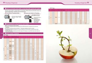
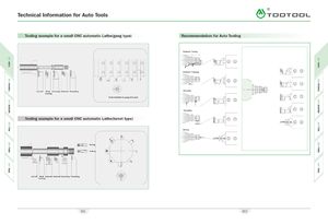
E Threading of Single-hole Threading of Single-hole E How to use Goose-neck holder on Automatic lathe (guide bush system) TKFT Type Goose-neck holder is applicable to automatic lathes whose toolholder does not Thread Type Pitchmm/TPIDescription Corner-R(re) Total ap(mm) No. ofPasses 1 2 3 4 5 6 7 8 9 10 move longitudinal direction ( Z-axis direction) 0.20mm 0.20 4 0.08 0.06 0.04 0.02 •Conventional Threading Holder # Goose-neck Holder for Threading 0.25mm 0.24 4 0.10 0.08 0.04 0.020.30mm0.2850.080.070.070.040.02 \9/ r Chips may bush and surface come into guide scratch thread \3 up to 15mm (1216 type)up to 19mm (1620 type)Goose-neck Holder is7javailable forthreading without 0.35mm 0.32 5 0.10 0.09 0.07 0.04 0.020.40mm0.3550.120.100.070.040.02m0.45mm0.3950.160.100.070.040.02CD032CD0.50mmCTPT 11R/LA /B6 0 -0 0 50.050.3350.100.100.070.040.023-O0.60mm0.4060.100.100.080.060.040.0203CL0.70mm0.4860.100.100.100.100.060.02 returning tread part 0.75mm 0.52 7 0.10 0.10 0.10 0.08 0.07 0.05 0.02 into guide bush, 0.80mm 0.56 7 0.10 0.10 0.10 0.10 0.08 0.06 0.02 (thread length 1.00mm 0.71 8 0.15 0.15 0.12 0.10 0.08 0.06 0.03 0.02 15mm/19mm) 1.25mm 0.90 9 0.20 0.18 0.13 0.10 0.10 0.07 0.05 0.05 0.02 Precautions for using Goose-neck holder 1,50mm CTPT 11R/LN60-010 0.10 1.09 10 0.22 0.20 0.15 0.12 0.10 0.10 0.08 0.05 0.05 0.02 When use Goose-neck Holder ® Be careful of interference with back spindle because offset dimension is large than the coventional toolholders (D Be careful of interference with sub spindle =}> Toolholder installation position is limited. @ At simultaneous machining (balance cut and tool approach for next process), interference with other toolholder may occur. @ In some cases, such as specifying toolholder shape on NC display or using CAM, Goose-neck holder can not be drawn perfectly 191 ap & number of passes 192 TKFT Type Thread Type Pitch mm/TPI Description Corner- R(re) Total ap(mm) No. ofPasses 1 2 3 4 5 6 7 8 9 10 11 0.20mm 0.15 4 0.06 0.04 0.03 0.02 0.25mm 0.19 4 0.07 0.06 0.04 0.02 0.30mm 0.23 4 0.08 0.07 0.06 0.02 0.35mm TKFT 12R/L Max 0.05A/B60-000Flat0.27 5 0.08 0.07 0.06 0.04 0.02 0.40mm 0.30 5 0.10 0.08 0.06 0.04 0.02 0.45mm 0.34 6 0.10 0.08 0.06 0.04 0.04 0.02 0.38 6 0.10 0.10 0.07 0.05 0.04 0.02 0.50mm TKFT 12R/LA/B60-0050.05 0.33 5 0.10 0.10 0.07 0.04 0.02 TKFT 12R/L Max 0.05Metric0.60mmA/B60-000TKFT 12R/LA/B60-005Flat0.050.450.40760.100.100.080.06 0.05 0.04 0.020.100.100.080.060.040.02 m 0.70mm 0.48 6 0.10 0.10 0.10 0.10 0.06 0.02 CD03 0.75mm TKFT 12R/LA/B60-0050.05 0.52 7 0.10 0.10 0.10 0.08 0.07 0.05 0.02 1 3" 0.80mm 0.56 7 0.10 0.10 0.10 0.10 0.08 0.06 0.02 3 TKFT 12R/L1.00mmA/B60-005TKFT 12R/LN60-0100.050.100.710.66860.15 0.15 0.12 0.10 0.08 0.06 0.03 0.020.180.150.120.100.060.030.02 TKFT 12R/L1,25mmA/B60-005TKFT 12R/LN60-0100.050.100.900.85980.20 0.18 0.13 0.10 0.10 0.07 0.05 0.05 0.020.200.180.130.100.100.070.050.02 1,50mm TKFT 12R/LN60-010 0.10 1.04 10 0.20 0.18 0.14 0.12 0.10 0.10 0.08 0.05 0.05 0.02 Parallel 28 TPI TKFT 12R/LPipe19 TPIA/B55-0050.050.671.01 79 0.18 0.15 0.12 0.10 0.06 0.04 0.020.200.180.140.120.120.100.080.050.02 24 TPI 0.79 8 0.18 0.18 0.12 0.10 0.08 0.07 0.04 0.02 20 TPIWhitworth18 TPITKFT 12R/LA/B55-0050.050.961.07 910 0.20 0.20 0.15 0.10 0.10 0.08 0.06 0.05 0.020.200.180.150.120.100.100.080.070.050.02 16 TPI 1.21 11 0.20 0.18 0.15 0.15 0.12 0.10 0.10 0.08 0.07 0.04 0.02