Общий каталог TooTool - страница 10
Навигация
 Каталог TooTool техническая информация 1
 Каталог TooTool монолитные фрезы
 Каталог TooTool техническая информация 2
- 页 1
- 页 2
- 页 3
- 页 4
- 页 5
- 页 6
- 页 7
- 页 8
- 页 9
- 页 10
- 页 11
- 页 12
- 页 13
- 页 14
- 页 15
- 页 16
- 页 17
- 页 18
- 页 19
- 页 20
- 页 21
- 页 22
- 页 23
- 页 24
- 页 25
- 页 26
- 页 27
- 页 28
- 页 29
- 页 30
- 页 31
- 页 32
- 页 33
- 页 34
- 页 35
- 页 36
- 页 37
- 页 38
- 页 39
- 页 40
- 页 41
- 页 42
- 页 43
- 页 44
- 页 45
- 页 46
- 页 47
- 页 48
- 页 49
- 页 50
- 页 51
- 页 52
- 页 53
- 页 54
- 页 55
- 页 56
- 页 57
- 页 58
- 页 59
- 页 60
- 页 61
- 页 62
- 页 63
- 页 64
- 页 65
- 页 66
- 页 67
- 页 68
- 页 69
- 页 70
- 页 71
- 页 72
- 页 73
- 页 74
- 页 75
- 页 76
- 页 77
- 页 78
- 页 79
- 页 80
- 页 81
- 82: 新增页码2
- 页 83
- 页 84
- 页 85
- 页 86
- 页 87
- 页 88
- 页 89
- 页 90
- 页 91
- 页 92
- 页 93
- 页 94
- 页 95
- 页 96
- 页 97
- 页 98
- 页 99
- 页 100
- 页 101
- 页 102
- 页 103
- 页 104
- 页 105
- 页 106
- 页 107
- 页 108
- 页 109
- 页 110
- 页 111
- 页 112
- 页 113
- 页 114
- 页 115
- 页 116
- 页 117
- 页 118
- 页 119
- 页 120
- 页 121
- 页 122
- 页 123
- 页 124
- 页 125
- 页 126
- 页 127
- 页 128
- 页 129
- 页 130
- 页 131
- 页 132
- 页 133
- 页 134
- 页 135
Technical information for Threading Technical information for Threading
GRADE & THEIR APPLICATIONS
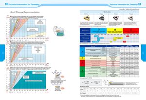
Anvil Change Recommendation Grade Use
TTIP30 TTIM45 TTIG30 TTIN30
Pitch
A Some Pitch to Diameter combinations require an Anvil change. If an Anvil change
TPI mm is required , use STM- R Anvils for EX-RH toolholders and for IN-LH boring bars.
Use STM-L Anvils for IN- RH toolholders and for EX-LH boring bars.
2.5 109 Special 5Holderv I I iACMESTUB ACME
3 83.57 Required v/ AC Co AC o£ ^V//o- rC *< V, 7 / TRAPEZ (DIN 103)ROUND (DIN 405) TiN coated , yellow color, the universal TiALN coated, black color; Multi-Layer The grade designation is according to Ceramic grade, good toughness, thegrade for general steel, recommendedPVD coated for stainless steel & steelfor rigid cutting conditional.medium machiningpressing thread inserts with new chip-breaker, compatible with all series ofstainless steel & steel < HRC 50medium machiningcollapse edge resistance and wearresistance. It is good for ordinary steelfinish to rough machining
4 6 CO/KZZ / 'T' Co RECOMMENDED SELECT FORTHREADING
5 5 ^/ Standard Anvil(Supplied With Holder)64 pWorkpiecesCarbon steel, alloy steelStailess steel, Heat tesistant
3.5 cast steel steel, Titanium alloy steel
8 3
10 2.5 iso 01 10 20 30 40 01 10 20 30 40
12 2161.5>77 Change to anvilSTM-R 1Nor STM-L 1N misftm
mm: 5 10 20 30 40 50 60 70 80 90 100 1 10 120 130 140Inch:0.250.500.7511.251.5022.50345Diameter PVD Coating 9
Pitch A Most applications use the standard Anvil supplied with the toolholder or boring bar. Ceramic IEKHB
TPI mm If an Anvil change is required, use STM- R Anvils for EX-RH toolholders and for IN-LH
boring bars. Use STM-L Anvils for IN- RH toolholders and for EX-LH boring bars. RECOMMEND CUTTING SPEED FORTHREADING
2.5 10 Q. 05