Общий каталог TooTool - страница 11
Навигация
 Каталог TooTool техническая информация 1
 Каталог TooTool монолитные фрезы
 Каталог TooTool техническая информация 2
- 页 1
- 页 2
- 页 3
- 页 4
- 页 5
- 页 6
- 页 7
- 页 8
- 页 9
- 页 10
- 页 11
- 页 12
- 页 13
- 页 14
- 页 15
- 页 16
- 页 17
- 页 18
- 页 19
- 页 20
- 页 21
- 页 22
- 页 23
- 页 24
- 页 25
- 页 26
- 页 27
- 页 28
- 页 29
- 页 30
- 页 31
- 页 32
- 页 33
- 页 34
- 页 35
- 页 36
- 页 37
- 页 38
- 页 39
- 页 40
- 页 41
- 页 42
- 页 43
- 页 44
- 页 45
- 页 46
- 页 47
- 页 48
- 页 49
- 页 50
- 页 51
- 页 52
- 页 53
- 页 54
- 页 55
- 页 56
- 页 57
- 页 58
- 页 59
- 页 60
- 页 61
- 页 62
- 页 63
- 页 64
- 页 65
- 页 66
- 页 67
- 页 68
- 页 69
- 页 70
- 页 71
- 页 72
- 页 73
- 页 74
- 页 75
- 页 76
- 页 77
- 页 78
- 页 79
- 页 80
- 页 81
- 82: 新增页码2
- 页 83
- 页 84
- 页 85
- 页 86
- 页 87
- 页 88
- 页 89
- 页 90
- 页 91
- 页 92
- 页 93
- 页 94
- 页 95
- 页 96
- 页 97
- 页 98
- 页 99
- 页 100
- 页 101
- 页 102
- 页 103
- 页 104
- 页 105
- 页 106
- 页 107
- 页 108
- 页 109
- 页 110
- 页 111
- 页 112
- 页 113
- 页 114
- 页 115
- 页 116
- 页 117
- 页 118
- 页 119
- 页 120
- 页 121
- 页 122
- 页 123
- 页 124
- 页 125
- 页 126
- 页 127
- 页 128
- 页 129
- 页 130
- 页 131
- 页 132
- 页 133
- 页 134
- 页 135
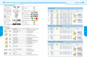
Technical information for Threading Thread Insert 01 Cutting Condition depending on Material Type c CDO Coolant Type Partial profile 60 oCD Material Dimension D OO CD Q- Pitch Dimensions I Diameter and LengthChipflow Character Holder Cross Section Area QCD. Designation Designation Picture(Right)(Left)(mm)(tpi)dLrxf Material Hardness £ Holder Overhang M 3ECDOverhang ER 11 - A60 EL 11 - A60 0.5-1.5 48-16 6.35 11 0.05 0.8 0.9 ~0V4External or Internalc-0 . 2oX Through Coolant Option ^j p, j 16 - A60CD 16 - A 60 0.5-1.5 48-16 9.525 16 0.05 0.8 0.9c16 - G6016 - G60- 1.753.014-89.525160.271.21.7 60M InternalCD16 - AG60X16 - AG600.5-3.048-89.525160.081.21.7LLU22 - N6022 - N603.5-5.07-512.7220.531.72.5 0 o‘o. Profile Shape Shank Type: CarbideQ. 27 - Q 60 27 - Q 60 - 5.5 6.0 4.5-4 15.875 27 0.64 2.1 3.127 - S 6027 - S 60- 5.58.0- 4.5415.875270.392.54.0 External < Surface Finish Carbide Implant Grade P M K IR 06 - A 60 IL 06 - A 60 0.5-1.25 48-20 3.97 6 0.04 0.6 0.6 08 -A60 08 - A 60 0.5-1.5 48-16 4.76 8 0.05 0.6 0.7 CDc 1 1 - A60 1 1 - A60 0,5-1.5 48-16 6.35 11 0.05 0.8 0.9 60S Internal Machine Stability -4 J Profile Shape: Pitch and Depth UQCDCDcCOccoMax. RPMRPMnNose RadiusCD CD 16 - A60 16 - A60 0.5-1.5 48-16 9.525 16 0.05 0.8 0.9 Lc16 -G6016 - G601.75-3.014-89.525160.161.21.716 - AG6016 - AG600.5 — 3.048-89.525160.051.21.722 - N6022 - N603.5-5.07-512.7220.301.72.5External 27 - Q60 27 - Q 60 5.5-6.0 4.5-4 15.875 27 0.30 1.8 2.7 Clamping System Stability Chipbreaker Style 27-S60 27 - S 60 - 5.5 8.0 4.5-4 15.875 27 0.39 2.5 4.0 Partial profile 60 0 (M Chip Breaker) Trouble Shooting Pitch Dimensions Problem Possible Cause Solution QCD. Designation(Right) Designation(Left) (mm) (tpi) d L r x f Picture Cutting speed too hight >- Reduce cutting speed/ use coated insert Increased Depth of cut too low/too many passes >- Increase the depth of cut per pass ERM 16 - A60 0.5— 1.5 48-16 9.525 16 0.05 0.8 0.9 017 flank wear Unsuitable carbide grade -> Use a coated carbide gradeInsu f ficient cooling>-Increase coolant flow rate 16 - G60 - 1.75 3.0 14-8 9.525 16 0.27 1.2 1.7 018CDc16 - AG600.5-3.048-89.525160.081.21.760KInternalCDx22- N603.5-5.07-512.7220.531.72.5L LU Uneven Incorrect helix angle -> Choose the correct shim External cutting edge wear Wrong infeed method -> Use the Alternating Flank Infeed method IRM 11 - A 60 0.5— 1.5 48-16 6.35 11 0.08 0.8 0.9 Depth olf cut too large — Decrease depth of cut/ increase number of passes 16 - A 60 - 0.5 1.5 48-16 9.525 16 0.08 0.8 0.9 InternalCDc16 - G601.75-3.014-89.525160.121.21.760S Extreme Insu f ficient cooling >- Increase coolant flow rate CD 16 - AG60 0.5-3.0 48-8 9.525 16 0.08 1.2 1.7 plastic Cutting speed too high - >- Reduce cutting speed c 22- N60 - 3.5 5.0 7-5 12.7 22 0.30 1.7 2.5 deformation Unsuitable carbide grade -> Use a tougher carbide Nose radius too small — -> Use an insert with a larger radius, if possible External Depth of cut too large -> Decrease depth of cut/ increase number of passes. Cutting Extreme plastic deformation -> Use a tougher carbide Partial profile 60° (U Chip Breaker) edge Insu f ficient cooling -> Increase flow rate and/ or correct flow direction breakage Unsuitable carbide grade — -> Use a tougher carbide Instability -> Check stability of the system Pitch Dimensions QCD. Designation(Right) Designation(Left) (mm) (tpi) d L r x f Picture Built - up Incorrect cutting speed - >- Change the cutting speed edge Unsuitable carbide grade >- Use a coated carbide ERU 16-A60 0 -.5 1.5 48-16 9.525 16 0.08 0.8 0.9 16-G60 1. -75 3.0 14-8 9.525 16 0.27 1.2 1.7 CDc 16-AG60 0.5-3.0 48-8 9.525 16 0.08 1.2 1.7 Interna60° The tool is not at the workpiece axis height >- Change tool height CD 22-N60 - 3.5 5.0 7-5 12.7 22 0.53 1.7 2.5 Thread profileis too shallowInsert is not machining the thread crest— -> Measure the workpiece diameter XLU L Worn insert -> Change the cutting edge sooner External IRU 16-A60 - 0.5 1.5 48-16 9.525 16 0.08 0.8 0.9 Poor Too low cutting speed >- Increase cutting speed 16-G60 1. -75 3.0 14-8 9.525 16 0.12 1.2 1.7 r -X Internal surface Wrong shim ->- Choose correct shim CDc 16-AG60 0. -5 3.0 48-8 9.525 16 0.08 1.2 1.7 60° quality Flank infeed method is not appropriate >- Use the alternate flank or radial infeed method CD 22-N60 3.5-5.0 7-5 12.7 22 0.30 1.7 2.5c External