Общий каталог TooTool - страница 97
Навигация
 Каталог TooTool техническая информация 1
 Каталог TooTool монолитные фрезы
 Каталог TooTool техническая информация 2
- 页 1
- 页 2
- 页 3
- 页 4
- 页 5
- 页 6
- 页 7
- 页 8
- 页 9
- 页 10
- 页 11
- 页 12
- 页 13
- 页 14
- 页 15
- 页 16
- 页 17
- 页 18
- 页 19
- 页 20
- 页 21
- 页 22
- 页 23
- 页 24
- 页 25
- 页 26
- 页 27
- 页 28
- 页 29
- 页 30
- 页 31
- 页 32
- 页 33
- 页 34
- 页 35
- 页 36
- 页 37
- 页 38
- 页 39
- 页 40
- 页 41
- 页 42
- 页 43
- 页 44
- 页 45
- 页 46
- 页 47
- 页 48
- 页 49
- 页 50
- 页 51
- 页 52
- 页 53
- 页 54
- 页 55
- 页 56
- 页 57
- 页 58
- 页 59
- 页 60
- 页 61
- 页 62
- 页 63
- 页 64
- 页 65
- 页 66
- 页 67
- 页 68
- 页 69
- 页 70
- 页 71
- 页 72
- 页 73
- 页 74
- 页 75
- 页 76
- 页 77
- 页 78
- 页 79
- 页 80
- 页 81
- 82: 新增页码2
- 页 83
- 页 84
- 页 85
- 页 86
- 页 87
- 页 88
- 页 89
- 页 90
- 页 91
- 页 92
- 页 93
- 页 94
- 页 95
- 页 96
- 页 97
- 页 98
- 页 99
- 页 100
- 页 101
- 页 102
- 页 103
- 页 104
- 页 105
- 页 106
- 页 107
- 页 108
- 页 109
- 页 110
- 页 111
- 页 112
- 页 113
- 页 114
- 页 115
- 页 116
- 页 117
- 页 118
- 页 119
- 页 120
- 页 121
- 页 122
- 页 123
- 页 124
- 页 125
- 页 126
- 页 127
- 页 128
- 页 129
- 页 130
- 页 131
- 页 132
- 页 133
- 页 134
- 页 135
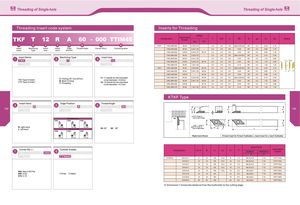
Threading of Single-hole Threading of Single-hole Threading Insert code system Inserts for Threading APMX Designation Applicablethread T CW H RE 0 cpd SI S2 Shape mm TPI 7w 8w CTPT 11R/L A60-000 M UN 0.20-0.75 2.5 2.5 8.0 Max 0.05 Flat 60° 5.2 0.40 2.10 Insert Machining Insert Insert Edge Thread Angle Corner-R(r £) Carbide grades 11R/L A60-005 M UN 0.40-1.25 2.5 2.5 8.0 0.05 60° 5.2 0.80 1.70 name Type size hand position 11R/L A55-005 GR W 0.20-0.75 48-16 2.5 2.5 8.0 0.05 55° 5.2 0.80 1.70 11R/L B60-000 M UN 0.20-0.75 2.5 2.5 8.0 Max 0.05 Flat 60° 5.2 2.10 0.40 Insert Name Machining Type Insert size 11R/L B60-005 M UN 0.40-1.25 2.5 2.5 8.0 0.05 60° 5.2 1.70 0.80 11R/L B55-005 GR W 0.20-0.75 48-16 2.5 2.5 8.0 0.05 55° 5.2 1.70 0.80 RE —T RE RE^/1 11R/L N60-010 M UN 1.00-1.50 2.5 2.5 8.0 0.10 60° 5.2 1.25 1.25 j _J TKFT 12R/L A60-000 M UN 0.20-0.60 64-48 3.0 2.5 8.7 Max 0.05 Flat 60° 5.2 0.40 2.10 7 12R/L A60-005 M UN 0.50-1.25 48-24 3.0 2.5 8.7 0.05 60° 5.2 0.80 1.70 e- cwl 12R/L A55-005 GR W 40-16 3.0 2.5 8.7 0.05 55° 5.2 0.80 1.70 TKF Type of insertCTP Type of insert C: Parting off / Cut-off lineB: Back TurningT: Threading 11: 11 stands for the inscribedcircle diameter = 8.0mm12: 12 stands for the inscribedcircle diameter = 8.7mm12R/L B60-000 M UN 0.20-0.60 64-48 3.0 2.5 8.7 Max 0.05 Flat 60° 5.2 2.10 0.4012R/L B60-005M UN0.50-1.2548-243.02.58.70.0560°5.21.700.8012R/L B55-005GR W40-163.02.58.70.0555°5.21.700.80 12R/L N60-010 M UN 1.00-1.50 24-18 3.0 2.5 8.7 0.10 60° 5.2 1.25 1.25 KTKF Type Insert Hand Edge Position Thread Angle T. 60 189 UL o u. m 190 sr F3 A Type \t hand (R) insertB TypefiNType P. AJAi/ rr KTKFR/L1616M-16 only for above shape I LIKTKF/1010K-12 R: right handL: left hand TKFT12RA . TKFT12RB.. TKFT12RN..Left hand (L) insert55: 55°60!60° KFR/L1010K - 16inly for right shape CM L1* A Type B Type N Type J) /i J) •Right-hand Shown R-hand Insert for R-hand Toolholder, L-hand Insert for L-hand Toolholder. TKFT12LA. TKFT12LB . TKFT12LN. Spart Parts Corner-Rfre ) Carbide Grades Designation H1=h B L1 L2 F1 T* ApplicableSCREWWRENCHInserts s fi KTKFR/L 0810-K11 8 10 125 15.0 8 7.0 M4.0x10.0 T-15 CTPT11R/L 1010-K11 10 10 125 15.0 10 7.0 M4.0x10.0 T-15 CTPT11R/L 1212-K11 12 12 125 15.0 12 7.0 M4.0x12.0 T-15 CTPT11R/L 1616-K11 16 16 125 15.0 16 7.0 M4.0x12.0 T-15 CTPT11R/L 000: Max 0.05 Flat 1010-K12 10 10 125 15.0 10 6.0 M4.5x9.0 T-15 TKFT12R/L 005: 0.05 TTIP30 TTIM45 1212-F12 12 12 85 12 6.0 M4.5x9.0 T-15 TKFT12R/L 010: 0.10 1212-M12 16 16 150 16 6.0 M4.5x9.0 T-15 TKFT12R/L 1616-M12 20 20 150 20 6.0 M4.5x9.0 T-15 TKFT12R/L Dimension T shows the distance from the toolholder to the cutting edge.