Общий каталог TooTool - страница 33
Навигация
 Каталог TooTool техническая информация 1
 Каталог TooTool монолитные фрезы
 Каталог TooTool техническая информация 2
- 页 1
- 页 2
- 页 3
- 页 4
- 页 5
- 页 6
- 页 7
- 页 8
- 页 9
- 页 10
- 页 11
- 页 12
- 页 13
- 页 14
- 页 15
- 页 16
- 页 17
- 页 18
- 页 19
- 页 20
- 页 21
- 页 22
- 页 23
- 页 24
- 页 25
- 页 26
- 页 27
- 页 28
- 页 29
- 页 30
- 页 31
- 页 32
- 页 33
- 页 34
- 页 35
- 页 36
- 页 37
- 页 38
- 页 39
- 页 40
- 页 41
- 页 42
- 页 43
- 页 44
- 页 45
- 页 46
- 页 47
- 页 48
- 页 49
- 页 50
- 页 51
- 页 52
- 页 53
- 页 54
- 页 55
- 页 56
- 页 57
- 页 58
- 页 59
- 页 60
- 页 61
- 页 62
- 页 63
- 页 64
- 页 65
- 页 66
- 页 67
- 页 68
- 页 69
- 页 70
- 页 71
- 页 72
- 页 73
- 页 74
- 页 75
- 页 76
- 页 77
- 页 78
- 页 79
- 页 80
- 页 81
- 82: 新增页码2
- 页 83
- 页 84
- 页 85
- 页 86
- 页 87
- 页 88
- 页 89
- 页 90
- 页 91
- 页 92
- 页 93
- 页 94
- 页 95
- 页 96
- 页 97
- 页 98
- 页 99
- 页 100
- 页 101
- 页 102
- 页 103
- 页 104
- 页 105
- 页 106
- 页 107
- 页 108
- 页 109
- 页 110
- 页 111
- 页 112
- 页 113
- 页 114
- 页 115
- 页 116
- 页 117
- 页 118
- 页 119
- 页 120
- 页 121
- 页 122
- 页 123
- 页 124
- 页 125
- 页 126
- 页 127
- 页 128
- 页 129
- 页 130
- 页 131
- 页 132
- 页 133
- 页 134
- 页 135
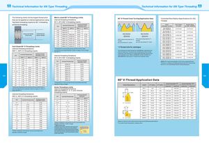
Technical Information for XN Type Threading Technical Information forXN Type Threading The following charts list the largest thread pitch Metric-sized 60° V-Threading Limits 60° V-Thread Crest Turning Application Data Controlled Root Radius Specifications for UNJ that can be applied on internal applications using internal threading limitations Threads Top Notch threading inserts for 60° V-threading NT-1, NT-2 60° V-threading inserts and Acme threading. TPI nominal thread size minimum threaddiameter (mm) insert nose radius thread radiuscatalogue numberon insertper MIL-S-8879A XNT-1 XNT-2 XNT-1 XNT-2 XNJ-3020R/L8XNJP-3020R/L80,477/0,502 0,477/0,574 4.00 M48 x 4.00 43.67 3.00 M42x 3.00 38.75 XNJ-3014R/L12XNJP-3014R/L120,317/0,342 0,317/0,381 minimum minor diameter nominal thread size 2.50 M39x2.50 M24x2.50 36.29 21.29(minimum bore)(maximum diameter)2.00M33x2.00M15X2.0030.8412.84 feed direction feed direction XNJ-3010R/L16XNJP-3010R/L160 , 238 / 0,2 6 4 0,238/0,287 1.75 M32x1.75 M15X1.75 30.11 13.11 XNTC crest turning insert for 12 NTC crest turning insert for 11 XNJF-3012R/L14XNJK-3012R/L140,271/0,297 0,271/0,327 1.50 M32x1.50 M15x1.50 30.38 13.381.25M29x1.25M14x1.2527.6512.65 threads threadsper inch and finer (P <2mm)per inch and coarser (P >3mm)XN JF-3010R / L16XNJK-3010R/L160 , 238 / 0,2640,238/0,287 1.00* M27x1.00 M14X1.00 25.92 12.92 XNJF-3009R/L18XNJK-3009R/L180 , 210 / 0,2 3 6 0,210/0,254 Inch-Sized 60° V-Threading Limits 0.75 M22x0.75 M12x0.75 21.19 11.19internal threading limitations* Thread pitch of 1mm and less can be cut with an XNT-2 insert“J”thread note for catalogue XNJF-3008R/L20XNJK-3008R/L200,190/0,215 0,190/0,228 XNT-1, XNT-2 V-threading inserts provided the core thread diameter is 25mmorlarger (11mmorlargerwith XNT-1). The controlled root radius thread form (SAE8879C) is defined for theexternal thread only. To machine the corresponding internal thread,XNJF-3007R/L24XNJK-3007R/L240 , 1 6 0 / 0,1 8 50,160/0,190 TPI nominal thread size minimum minordiameter (inch)internal threading limitationsXNT-1XNT-2X N T- 1XNT-2NT-3, NT-4 60° V-threading inserts choose any insert that will cut a unified class 2B thread, then bore theminor diameter to size. Refer to SAE8879C and MIL-S-8879C andXNJF-3006R/L28XNJK-3006R/L280 , 1 3 7 / 0,1 6 20,137/0,162SAEAS8879D for the correct “J” thread minor diameter values.XNJF-3005R/L32XNJK-3005R/L320 , 1 1 9 / 0,1 4 20,119/0,142 6 1-7/8 1.695 7 1-3/4 1.595 TPI nominal thread size minimum threaddiameter (mm) NOTE: NTC inserts automatically control root to crest dimensions. 8 1-5/8 1.490 6.00** M76x 6.00 69.50 Therefore, in setting up threading operations with NTC inserts,checkthe O.D. or I.D. at the thread crest for correct dimensions. 9 1-9/16 1.442 5.50** M73x 5.50 67.05 10 1-1/2 15/16 1.392 0.830 5.00 M70x 5.00 64.59 11 1- 7 / 1 6 15/16 1.339 0.830 4.00 M64x4.00 59.67 11- 1/ 2 1-3/8 15/16 1.281 0.830 3.00 M52x3.00 48.75 12 1-3/8 9/16 1.285 0.472 2.50 M48x2.50 45.29 061 13 1-5/16 9/16 1.229 0.472 2.00 M42x2.00 39.84 062 14 1-1/4 9/16 1.173 0.472 1.75 M40x1.75 38.11 16 1-1/4 9/16 1.182 0.472 1.50* M38x1.50 36.38 60° V-Thread Application Data 18 1-1/8 9/16 1.065 0.472 20 1-1/8 1/2 1.071 0.440 *Thread pitch of 1,5mm and less can be cut provided core threaddiameter is 35mm or larger.24*/1-1/161121.0170.440 recommended TP* recommended TPI*Insert DescriptioninsertD* (mm)E* (mm)externalintertnalexternalintertnal *Twenty-four threads per inch and finer can be cut with an XNT-2 Acme Threading Limits insert provided the minor diameter is 25mm or larger (11,18mm or internal threading limitations E XNT-1 1.90 1.11 1.00-2.00 24-12 larger with XNT-1). XNAand XNAS-2, -3, -4, and -6 Acme XNT-2 28.70 1.90 0.70-3.00 1.25-3.50 36-8 20-7 threading insertsinternal threading limitations minimum thread J radius XNTF-2 15.75 1.01 0.60-1.75 1.00-2.00 44-14 24-12D XNT-3, XNT-4 V-threading inserts TPI nominal thread size diameter XNTK-2 15.75 1.01 0.60-1.75 1.00-2.00 44-14 24-12NT- TPI nominal thread size minimum minordiameter (inch) XNT-1 XNT-22*54.500114.30 NTP- XNTP-2 28.70 1.90 0.70-3.00 1.25-3.50 36-8 20-7NT-KNT-CX N T- 337.592.461.25-4.002.00-5.0020-612-5 4** 3 2.792 2-1/2* 4-1 1 2 4.100 104.10 feed direction XNTF-3 21.08 1.37 0.60-2.50 1.00-2.50 44-10 24-9 4-1/2** 2-7/8 2.634 3** 4 3.665 93.10 5 2-3/4 2.534 4 3-1 / 2 3.250 82.6062-1/22.320532.80071.10 Er XNTK-3 21.08 1.37 0.60-2.50 1.00-2.50 44-10 24-9XNTP-337.592.461.25-4.002.00-5.0020-612-5 7 2-1/4 2.095 6 2-1 / 2 2.333 59.30 X N T- 4 49.78 3.22 1.25-6.25 2.00-6.25 20-4 12-4 8 2 1.865 8 2-1/4 2.125 54.00 XNTF-4 21.08 1.37 0.60-2.50 1.00-2.50 44-10 24-9 9 1-15/16 1.817 10 2 1.900 48.30 XNTK-4 21.08 1.37 0.60-2.50 1.00-2.50 44-10 24-9 10 1-7/8 1.767 12 1-3/4 1.667 42.40 11 1-13/16 1.714 14 1-5/8 1.554 39.5 feed direction XNTP-4 49.78 3.22 1.25-6.25 2.00-6.25 20-4 12-5 11- 1/ 2 1-3/4 1.656 16* 1-1 1 2 1.438 36.5 *Based on maximum insert radius size and class 2Aand 2B thread specifications. 12 1-3/4 1.660 *Sixteen threads per inch and finer can be cut provided minor131-5/81.542diameter is 36,5mm (1.438") or larger. **For metric D and E dimensions, multiply by 25,4. **XNA-6 insert only. 14 1-9 / 1 6 1.485 Additional secondary clearance can be ground 16* 1-7/16 1.370 on leading edge of insert to provide sufficient helical clearance for machining coarser threads ^Sixteen threads per inch and finer can be cut provided minordiameter is 34,8mm or larger.and multistart threads. Modified standard insertsmay be furnished for machining threads outsideincreaseIT clearance of the limits shown.