Общий каталог TooTool - страница 34
Навигация
 Каталог TooTool техническая информация 1
 Каталог TooTool монолитные фрезы
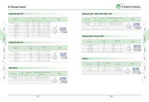 Каталог TooTool техническая информация 2
- 页 1
- 页 2
- 页 3
- 页 4
- 页 5
- 页 6
- 页 7
- 页 8
- 页 9
- 页 10
- 页 11
- 页 12
- 页 13
- 页 14
- 页 15
- 页 16
- 页 17
- 页 18
- 页 19
- 页 20
- 页 21
- 页 22
- 页 23
- 页 24
- 页 25
- 页 26
- 页 27
- 页 28
- 页 29
- 页 30
- 页 31
- 页 32
- 页 33
- 页 34
- 页 35
- 页 36
- 页 37
- 页 38
- 页 39
- 页 40
- 页 41
- 页 42
- 页 43
- 页 44
- 页 45
- 页 46
- 页 47
- 页 48
- 页 49
- 页 50
- 页 51
- 页 52
- 页 53
- 页 54
- 页 55
- 页 56
- 页 57
- 页 58
- 页 59
- 页 60
- 页 61
- 页 62
- 页 63
- 页 64
- 页 65
- 页 66
- 页 67
- 页 68
- 页 69
- 页 70
- 页 71
- 页 72
- 页 73
- 页 74
- 页 75
- 页 76
- 页 77
- 页 78
- 页 79
- 页 80
- 页 81
- 82: 新增页码2
- 页 83
- 页 84
- 页 85
- 页 86
- 页 87
- 页 88
- 页 89
- 页 90
- 页 91
- 页 92
- 页 93
- 页 94
- 页 95
- 页 96
- 页 97
- 页 98
- 页 99
- 页 100
- 页 101
- 页 102
- 页 103
- 页 104
- 页 105
- 页 106
- 页 107
- 页 108
- 页 109
- 页 110
- 页 111
- 页 112
- 页 113
- 页 114
- 页 115
- 页 116
- 页 117
- 页 118
- 页 119
- 页 120
- 页 121
- 页 122
- 页 123
- 页 124
- 页 125
- 页 126
- 页 127
- 页 128
- 页 129
- 页 130
- 页 131
- 页 132
- 页 133
- 页 134
- 页 135
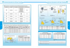
Technical Information for XN Type Threading Technical Information forXN Type Threading API Thread Forms •Insert Applications Chart for API Rotary Shouldered Connections chuck chuck Insert vs. Toolholder Orientation Thread form cresting non-cresting tool joint application minimum box size* anti-clockwise rotation anti-clockwise rotation externalinternal 2-3/8 API internal flush2-7/8 API internal flush3-1/2 API internal flush4 API internal flushV-.038R2" TPF4 TPIXNDC-4038R/L24-E/IR4API382XND-3038R/L4-1/2 API internal flush5-1/2 API internal flush6-5/8 API internal flushAPI #312-7/8 IF4 API full hole__7° pressure flankof the thread beingthe leading flankfeeifeedXNTB-2LA-7°'lXNTB-3LAXNTB-4LAIT7° XNTB-2RA r iiiXNTB-3RAiseatingsurfacein barXNTB-4RAI/seating surfacinsert API #23, API #26, API #31,API #35, API #38, API #40,API #44, API #46, API #50 XNTB-2RA 7° pressure flank ^’irTtoolholder ~ "notchXNTB-3RAof the thread beingthe leading flankinsert XNTB-4RAV-.038R3" TPF4 TPIXNDC-4038R/L34-E/IR4API383XND-3038R/LAPI #56API #61API #70API #77API #56 notch NTB-2LANTB-3LANTB-4LA External Buttress Internal Buttress V- . 0 5 02" TPF4 TPI XNDC -4050 R /L24-E/IRAPI502XND -4050 R /L 5-1/2 API full hole6-5/8 API regular6-5/8 API full hole5-1/2 API full hole 7° pressure flank leading 7° pressure flank leading Reference Dimensions Infeed Angle vs. Chip Load: 7° Pressure Flank Leading V-.0503" TPF4 TPI XNDC-4050R/L34-E/IR4API503 XND -4050 R /L 5-1/2 API regular7-5/8 API regular8-5/8 API regular5-1/2 API regular h— A .010" infeed.010" infeedi nose radius .0039" .0052" T .007" chip load V- . 0 4 03" TPF5 TPI XNDC-3040R/L3XNDC-4040R/L34-E/IR5API403XND-3040R/LXND -4040 R /L 2-3/8 API regular2-7/8 API regular3-1/2 API regular4-1/2 API regular3-1/2 API regular chip loac chip load .0012"-Dchip loadmaximum depth with A-style insert *Minimum box size that can be threaded with a standard Top Notch insert due to minimum bore equipment. 15° infeed angle XNTB-A insert 0° infeed angle feed direction feed direction 063 API Thread Forms •Product Thread Dimensions •Rotary Shouldered Connections (Inch) 064 Threadform taper inchper ft threadheight,nottruncatedHthreadheight,truncatedhn=hstr root uncation Sm— Srs fm — frs tr crest uncation fcn=fcswidth of flatcrestcrestfen—fesfm=frsrootradiusrm=rsradius atthreadcornersrpitchP Insert D( inch ) A nose radius pitch based on( inch )(inch)maximum radiusXNTB-20.1330.0240.002-0.00416-20 TPIXNTB-30.1710.0310.005-0.0088-16 TPI XNTB-4 0.218 0.049 0.008-0.012 4-6 TPI V- 0 . 3 8 R 2 0.216005 0.121844 0.038000 0.056161 0.065 0.038 0.015 0.250 NOTE: For balanced chip load, 15° infeed angle is suggested. V-0.38R 3 0.215379 0.121381 0.380000 0.055998 0.065 0.038 0.015 V-0.40 3 0.172303 0.117842 0.200000 0.034461 0.040 0.020 0.015 0.250V-0.5030.2153790.1473030.2500000.0430760.0500.0250.015Internal Threading Limitations V-0.50 2 0.216005 0.147804 0.250000 0.043201 0.050 0.025 0.015 0.250 internal threading limitations internal threading limitations NOTE: All dimensions in inches. XNTB-2A Buttress threading inserts XNTB-3 and XNTB-4A Buttress threading inserts TPI nominal thread size minimum minordiameter (inch) TPI nominal thread size minimum minordiameter (inch) 8 1-3/4 1.600 4* 2-1/2 2.200 V-.040 and V-.050 Product Thread Form Casing and Tubing Round Thread 10 1-5/8 1.505 5 2-1/4 2.010 (Height Dimensions) 12 1-1/2 1.400 6 2 1.800 PboxiHtv,I\>\r ,^CS^CS thread element 10 TPI 8 TPIp=.1000p=.1250H=.866p0.086600.10825Hs=hs= .626p - . 0070.055600.07125Srs—Sm= .1 2 0 p +. 0 0 20.014000.01700161-1/4 1.175 8 1-3/4 1.600201-1/161.002101-5/81.50512**1-1/ 21.400*NTB-4A insert only.**Can cut 16 or 20 threads per inch provided minor diameter is 1.375"or larger. 1 Scs— Sen =.120p+.005 0.17000 0.02000 f,cnaxis of thread /pin 90° i Threads per Inch vs. Maximum Root Radius Chart (Inch)TPI20 16 12 10 8 6 5 4 3 2-1/2 2.0 1-1/2 1-1/4 1 maximum root 0.0036 0.0045 0.0059 0.0071 0.0089 0.1190 0.0143 0.0179 0.0238 0.0286 0.3750 0.0476 0.0572 0.0714 radius NOTE: Special Buttress forms are available upon request.