Общий каталог TooTool - страница 95
Навигация
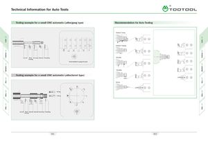 Каталог TooTool техническая информация 1
 Каталог TooTool монолитные фрезы
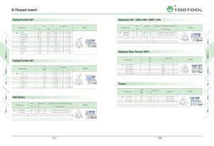 Каталог TooTool техническая информация 2
- 页 1
- 页 2
- 页 3
- 页 4
- 页 5
- 页 6
- 页 7
- 页 8
- 页 9
- 页 10
- 页 11
- 页 12
- 页 13
- 页 14
- 页 15
- 页 16
- 页 17
- 页 18
- 页 19
- 页 20
- 页 21
- 页 22
- 页 23
- 页 24
- 页 25
- 页 26
- 页 27
- 页 28
- 页 29
- 页 30
- 页 31
- 页 32
- 页 33
- 页 34
- 页 35
- 页 36
- 页 37
- 页 38
- 页 39
- 页 40
- 页 41
- 页 42
- 页 43
- 页 44
- 页 45
- 页 46
- 页 47
- 页 48
- 页 49
- 页 50
- 页 51
- 页 52
- 页 53
- 页 54
- 页 55
- 页 56
- 页 57
- 页 58
- 页 59
- 页 60
- 页 61
- 页 62
- 页 63
- 页 64
- 页 65
- 页 66
- 页 67
- 页 68
- 页 69
- 页 70
- 页 71
- 页 72
- 页 73
- 页 74
- 页 75
- 页 76
- 页 77
- 页 78
- 页 79
- 页 80
- 页 81
- 82: 新增页码2
- 页 83
- 页 84
- 页 85
- 页 86
- 页 87
- 页 88
- 页 89
- 页 90
- 页 91
- 页 92
- 页 93
- 页 94
- 页 95
- 页 96
- 页 97
- 页 98
- 页 99
- 页 100
- 页 101
- 页 102
- 页 103
- 页 104
- 页 105
- 页 106
- 页 107
- 页 108
- 页 109
- 页 110
- 页 111
- 页 112
- 页 113
- 页 114
- 页 115
- 页 116
- 页 117
- 页 118
- 页 119
- 页 120
- 页 121
- 页 122
- 页 123
- 页 124
- 页 125
- 页 126
- 页 127
- 页 128
- 页 129
- 页 130
- 页 131
- 页 132
- 页 133
- 页 134
- 页 135
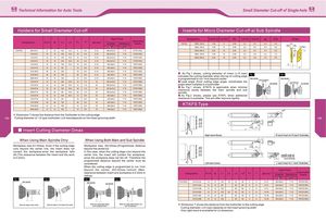
Technical Information for Auto Tools Small Diameter Cut-off of Single-hole
Holders for Small Diameter Cut - off Inserts for Micro Diameter Cut - off at Sub Spindle
Spart Parts Designation CW ± 0.03 CUTDIA RE T ± 0.02 H ± 0.02 cpd CDX Shape
Applicable
Designation H1= h B L1 L2 F1 T* cpD max " cw
SCREW WRENCH Inserts TKFCS 12 R / L 100 - S 1.00 6 0.05 2.2 8.7 4.4 3.3
RER “ REL
"
12 R / L 150 - S 1.50 9 0.05 2.2 8.7 4.4 4.8 CUTDIA j
KTKFR / L 0810 - K 11 8 10 125 15.0 8 5.5 5 - 12 M 4.0 x 10.0 T- 15 CTPC 11 R / L 12R / L 200 - S 2.00 12 0.05 2.2 8.7 4.4 6.3 ‘
CDX
»,
0
1010 - K 11 10 10 125 15.0 10 5.5 5 - 12 M 4.0 x 10.0 T- 15 CTPC 11 R / L 16 R / L 150 - S 1.50 14 0.05 2.2 9.5 4.4 7.3
fl
J
1212 - K 11 12 12 125 15.0 12 5.5 5 - 12 M 4.0 x 12.0 T- 15 CTPC 11 R / L 16 R / L 200 - S 2.00 16 0.05 2.2 9.5 4.4 8.5
1616 - K 11 16 16 125 15.0 16 5.5 5 - 12 M 4.0 x 12.0 T - 15 CTPC 11 R / L
1010 - K 12 10 10 125 15.0 10 6.0 5 - 12 M 4.5 x 9.0 T-15 TKFC 12 R / L T
1212 - F 12 12 12 85 12 6.0 5 - 12 M 4.5 x 9.0 T-15 TKFC 12R / L H
1212 - M 12 16 16 150 16 6.0 5 - 12 M 4.5 x 9.0 T-15 TKFC 12R / L
1616 - M 12 20 20 150 20 6.0 5 - 12 M 4.5 x 9.0 T-15 TKFC 12R / L
As Fig . 1 shows , cutting diameter of insert ( 0 D max ) Fig. 1
indicates the cutting diameter when the top of cutting edge
2020 - M 12 10 10 150 10 8.0 5 - 12 M 4.5 x 9.0 T-15 TKFC 16 R / L
is programmed to run 1 mm beyond center Main Spindle Main Spindle
1010 -K 15 10 10 125 19.5 10 7.5 16 M 4.0 x 10.0 T-15 CTPC 15 R / L Lead angle ( front cutting edge angle : w ) indicates the / Long Distance
Sub Spindle Sub Spindle
angle when installed in a toolholder
1212 -K 15 12 12 125 19.5 12 7.5 16 M 4.0 x 12.0 T-15 CTPC 15 R / L
As Fig . 1 shows , KTKFS is applicable when minimal 7 TO
I i
jJ
o
1616 - K 15 16 16 125 19.5 16 7.5 16 M 4.0 x 12.0 T- 15 CTPC 15 R / L
clearance exists between the main spindle and sub
2020 - F 15 20 20 85 19.5 20 7.5 16 M 4.0 x 12.0 T- 15 CTPC 15 R / L
spindle .
1010 - K 16 12 12 125 20.0 12 8.0 16 M 4.5 x 9.0 T- 15 TKFC 16 R / L As Fig . 2 shows , please use KTKFL when additional
1212 - F 16 16 16 85 16 8.0 16 M 4.5 x 9.0 T - 15 TKFC 16 R / L clearance is available . This will offer improve rigidity.
1212 - M 16 20 20 150 20 8.0 16 M 4.5 x 9.0 T-15 TKFC 16 R / L
1616 - M 16 12 12 150 12 6.0 16 M 4.5 x 9.0 T-15 TKFC 12 R / L
KTKFS Type
2020 - M 16 12 12 150 12 8.0 16 M 4.5 x 9.0 T-15 TKFC 16 R / L
/
7
^
X
• * Dimension T shows the distance from the Toolholder to the cutting edge X C
185 Cutting diameter of - 12 type toolholder ( 0 D max ) depends on the insert grooving width Q
m 186
CD
Sy <
CD CD
L4
"
O
F < cd
Q- CM CM CO
- C/D 7- 7; T E
-Qzs o o
30? L3
C/D
Insert Cutting Diameter Dmax L1
t 1 Right-hand Shown R -hand Insert for R -hand Toolholder.
T
E
When Using Main Spindle Only When Using Both Main and Sub Spindle
m ?M
Workpiece max , D 1 = Dmax . Even if the cutting edge Workpiece max , D 2 = Dmax - ( Programmed distance o <m
runs beyond the center line , the insert does not beyond the center ) x 2 D CD CD
< L1
contact the workpiece , since the workpiece falls In this case , when the cutting dege runs beyond the 1
—
55 CM CM
&
CL
off . ( The clearance between the insert and the work center line , the insert will contact the workpiece I _
C/D
Q
o o
^
c^.
LO x -C KTKFSR/L1010K 12 A
3 KTKFSR/L1010K 16A
is 0.2 mm ) since the workpiece does not fall off . Therefore the C/D
CM L2 only for left shape
programmed distance beyond the center must be
considered .
t 4 Left-hand shown L -hand Insert for L-hand Toolholder.
When the cutting edge is programmed to run 1 mm
beyond the center , [ D 2 = Dmax - 1 mmx 2 ] ( Max . Spart Parts
clearance between insert and workpiece is 0.2 mm in Designation H 1 =h B L1 L2 L3 L4* F1 T cpD maxx Applicable
-
SCREW WRENCH Inserts
radius )
Fig. 1 Fig. 3 x
Main Spindle KTKFSR / L 1010 - K 12 A 10 10 125 15 22 26 5 6 6 - 12 M 4.5 x 9.0 T-15 TKFCS 12 R / L
Main Spindle
7 7
Sub Spindle
1
1212 - F 12 A 12 12 85 22 26 5 6 6 - 12 M 4.5 x 9.0 T-15 TKFCS 12 R / L
N CM
1212 - K 12 B 12 12 125 26 26 5 6 6 - 12 M 4.5 x 9.0 T- 15 TKFCS 12 R / L
X X w X
t 1010 - K 16 A
1212 - F 16 A
1212 - K 16 B
10
12
12
10
12
12
125
85
125
20 22
22
26
30
30
30
5
5
5
8
8
8
14 - 16
14 - 16
14 - 16
M 4.5 x 9.0
M 4.5 x 9.0
M 4.5 x 9.0
T- 15
T- 15
T- 15
TKFCS 16 R / L
TKFCS 16 R / L
TKFCS 16 R / L
When the edge is at the center . When the edge is 1mm beyond the center . When the cutting edge locates
at the workpiece center .
When the cutting edge exceeds 1 mm
over the workpiece.
Dimension T shows the distance from the toolholder to the cutting edge
Cutting diameter ( 0 D max ) depends on the insert grooving width
Only right - hand is available for L4 dimension
Holders for Small Diameter Cut - off Inserts for Micro Diameter Cut - off at Sub Spindle
Spart Parts Designation CW ± 0.03 CUTDIA RE T ± 0.02 H ± 0.02 cpd CDX Shape
Applicable
Designation H1= h B L1 L2 F1 T* cpD max " cw
SCREW WRENCH Inserts TKFCS 12 R / L 100 - S 1.00 6 0.05 2.2 8.7 4.4 3.3
RER “ REL
"
12 R / L 150 - S 1.50 9 0.05 2.2 8.7 4.4 4.8 CUTDIA j
KTKFR / L 0810 - K 11 8 10 125 15.0 8 5.5 5 - 12 M 4.0 x 10.0 T- 15 CTPC 11 R / L 12R / L 200 - S 2.00 12 0.05 2.2 8.7 4.4 6.3 ‘
CDX
»,
0
1010 - K 11 10 10 125 15.0 10 5.5 5 - 12 M 4.0 x 10.0 T- 15 CTPC 11 R / L 16 R / L 150 - S 1.50 14 0.05 2.2 9.5 4.4 7.3
fl
J
1212 - K 11 12 12 125 15.0 12 5.5 5 - 12 M 4.0 x 12.0 T- 15 CTPC 11 R / L 16 R / L 200 - S 2.00 16 0.05 2.2 9.5 4.4 8.5
1616 - K 11 16 16 125 15.0 16 5.5 5 - 12 M 4.0 x 12.0 T - 15 CTPC 11 R / L
1010 - K 12 10 10 125 15.0 10 6.0 5 - 12 M 4.5 x 9.0 T-15 TKFC 12 R / L T
1212 - F 12 12 12 85 12 6.0 5 - 12 M 4.5 x 9.0 T-15 TKFC 12R / L H
1212 - M 12 16 16 150 16 6.0 5 - 12 M 4.5 x 9.0 T-15 TKFC 12R / L
1616 - M 12 20 20 150 20 6.0 5 - 12 M 4.5 x 9.0 T-15 TKFC 12R / L
As Fig . 1 shows , cutting diameter of insert ( 0 D max ) Fig. 1
indicates the cutting diameter when the top of cutting edge
2020 - M 12 10 10 150 10 8.0 5 - 12 M 4.5 x 9.0 T-15 TKFC 16 R / L
is programmed to run 1 mm beyond center Main Spindle Main Spindle
1010 -K 15 10 10 125 19.5 10 7.5 16 M 4.0 x 10.0 T-15 CTPC 15 R / L Lead angle ( front cutting edge angle : w ) indicates the / Long Distance
Sub Spindle Sub Spindle
angle when installed in a toolholder
1212 -K 15 12 12 125 19.5 12 7.5 16 M 4.0 x 12.0 T-15 CTPC 15 R / L
As Fig . 1 shows , KTKFS is applicable when minimal 7 TO
I i
jJ
o
1616 - K 15 16 16 125 19.5 16 7.5 16 M 4.0 x 12.0 T- 15 CTPC 15 R / L
clearance exists between the main spindle and sub
2020 - F 15 20 20 85 19.5 20 7.5 16 M 4.0 x 12.0 T- 15 CTPC 15 R / L
spindle .
1010 - K 16 12 12 125 20.0 12 8.0 16 M 4.5 x 9.0 T- 15 TKFC 16 R / L As Fig . 2 shows , please use KTKFL when additional
1212 - F 16 16 16 85 16 8.0 16 M 4.5 x 9.0 T - 15 TKFC 16 R / L clearance is available . This will offer improve rigidity.
1212 - M 16 20 20 150 20 8.0 16 M 4.5 x 9.0 T-15 TKFC 16 R / L
1616 - M 16 12 12 150 12 6.0 16 M 4.5 x 9.0 T-15 TKFC 12 R / L
KTKFS Type
2020 - M 16 12 12 150 12 8.0 16 M 4.5 x 9.0 T-15 TKFC 16 R / L
/
7
^
X
• * Dimension T shows the distance from the Toolholder to the cutting edge X C
185 Cutting diameter of - 12 type toolholder ( 0 D max ) depends on the insert grooving width Q
m 186
CD
Sy <
CD CD
L4
"
O
F < cd
Q- CM CM CO
- C/D 7- 7; T E
-Qzs o o
30? L3
C/D
Insert Cutting Diameter Dmax L1
t 1 Right-hand Shown R -hand Insert for R -hand Toolholder.
T
E
When Using Main Spindle Only When Using Both Main and Sub Spindle
m ?M
Workpiece max , D 1 = Dmax . Even if the cutting edge Workpiece max , D 2 = Dmax - ( Programmed distance o <m
runs beyond the center line , the insert does not beyond the center ) x 2 D CD CD
< L1
contact the workpiece , since the workpiece falls In this case , when the cutting dege runs beyond the 1
—
55 CM CM
&
CL
off . ( The clearance between the insert and the work center line , the insert will contact the workpiece I _
C/D
Q
o o
^
c^.
LO x -C KTKFSR/L1010K 12 A
3 KTKFSR/L1010K 16A
is 0.2 mm ) since the workpiece does not fall off . Therefore the C/D
CM L2 only for left shape
programmed distance beyond the center must be
considered .
t 4 Left-hand shown L -hand Insert for L-hand Toolholder.
When the cutting edge is programmed to run 1 mm
beyond the center , [ D 2 = Dmax - 1 mmx 2 ] ( Max . Spart Parts
clearance between insert and workpiece is 0.2 mm in Designation H 1 =h B L1 L2 L3 L4* F1 T cpD maxx Applicable
-
SCREW WRENCH Inserts
radius )
Fig. 1 Fig. 3 x
Main Spindle KTKFSR / L 1010 - K 12 A 10 10 125 15 22 26 5 6 6 - 12 M 4.5 x 9.0 T-15 TKFCS 12 R / L
Main Spindle
7 7
Sub Spindle
1
1212 - F 12 A 12 12 85 22 26 5 6 6 - 12 M 4.5 x 9.0 T-15 TKFCS 12 R / L
N CM
1212 - K 12 B 12 12 125 26 26 5 6 6 - 12 M 4.5 x 9.0 T- 15 TKFCS 12 R / L
X X w X
t 1010 - K 16 A
1212 - F 16 A
1212 - K 16 B
10
12
12
10
12
12
125
85
125
20 22
22
26
30
30
30
5
5
5
8
8
8
14 - 16
14 - 16
14 - 16
M 4.5 x 9.0
M 4.5 x 9.0
M 4.5 x 9.0
T- 15
T- 15
T- 15
TKFCS 16 R / L
TKFCS 16 R / L
TKFCS 16 R / L
When the edge is at the center . When the edge is 1mm beyond the center . When the cutting edge locates
at the workpiece center .
When the cutting edge exceeds 1 mm
over the workpiece.
Dimension T shows the distance from the toolholder to the cutting edge
Cutting diameter ( 0 D max ) depends on the insert grooving width
Only right - hand is available for L4 dimension