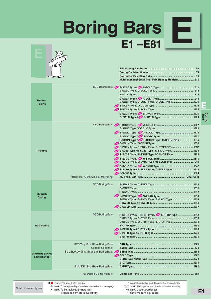
Каталог Sumitomo пластины с алмазными вставками Sumidia - страница 44
Навигация
 Каталог Sumitomo токарные резцы (державки) для внутреннего точения
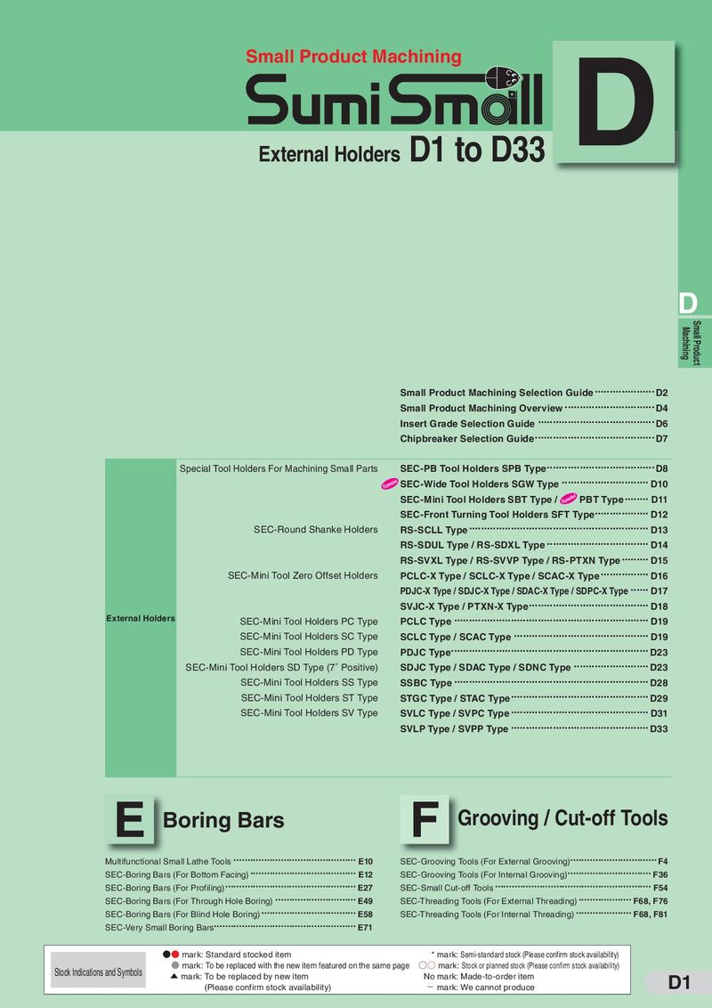 Каталог Sumitomo микроинструмент
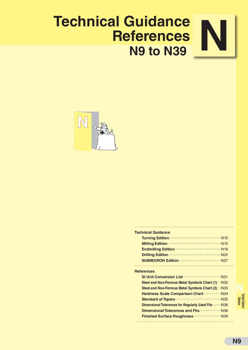 Техническая информация Sumitomo
 Каталог Sumitomo модульные системы для револьверных головок токарных станков
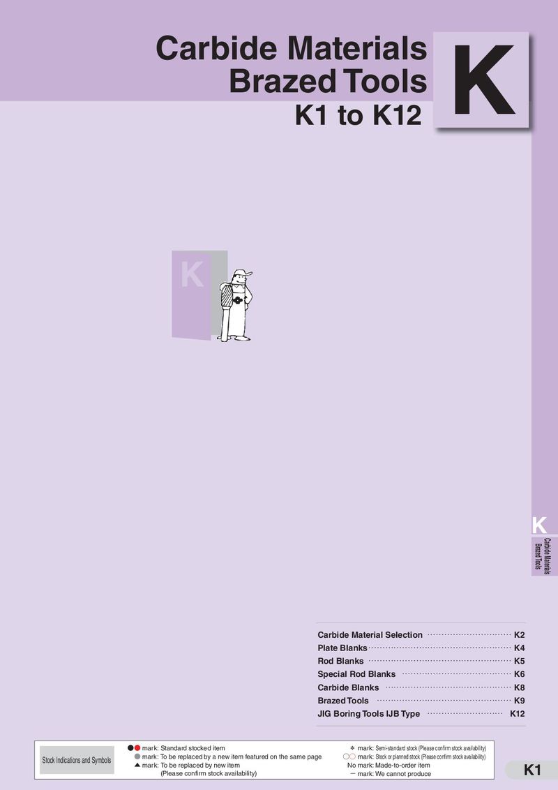 Каталог Sumitomo твердосплавные заготовки
 Каталог Sumitomo фрезы со сменными пластинами
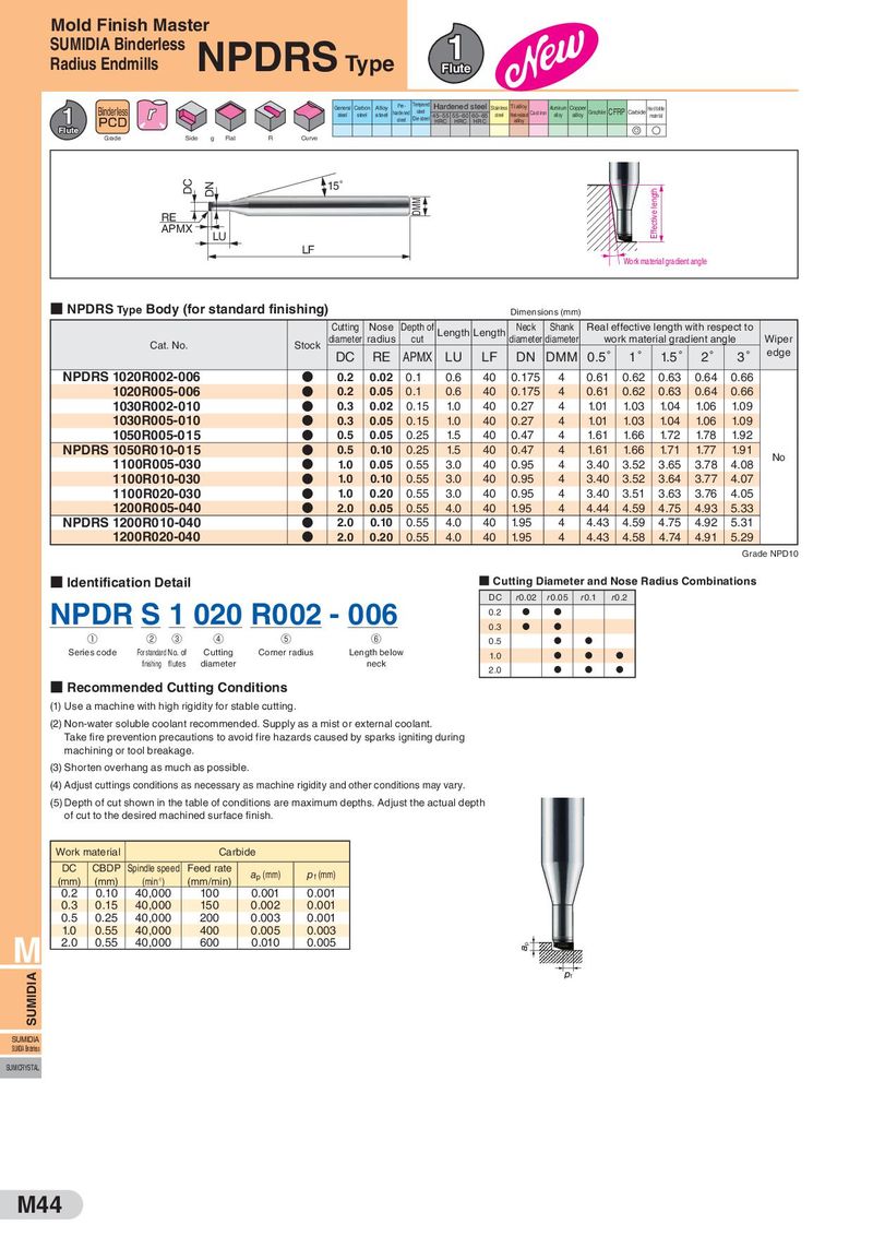
Mold Finish Master SUMIDIA Binderless NPDRS Type 1 Radius Endmills Flute Binderless General Carbon Alloy Pre- Tempered Hardened steel Stainless Ti alloy Aluminum Copper Hard brittle 1 steel steel steel hardened steel 45–55 55–60 60–65 steel Heat resistant Cast iron alloy alloy Graphite CFRP Carbide material PCD steel Die steel HRC HRC HRC alloy Flute G S Grade Side g Flat R Curve DC DN 15° Effective length RE DMM APMX LU LF Work material gradient angle ■ NPDRS Type Body (for standard finishing) Dimensions (mm) Cutting Nose Depth of Length Length Neck Shank Real effective length with respect to Cat. No. Stock diameter radius cut diameter diameter work material gradient angle Wiper DC RE APMX LU LF DN DMM 0.5 1 1.5 2 3 edge NPDRS 1020R002-006 D 0.2 0.02 0.1 0.6 40 0.175 4 0.61 0.62 0.63 0.64 0.66 1020R005-006 D 0.2 0.05 0.1 0.6 40 0.175 4 0.61 0.62 0.63 0.64 0.66 1030R0 02-0 10 D 0.3 0.02 0.15 1.0 40 0.27 4 1.01 1.03 1.04 1.06 1.09 1030R0 05-0 10 D 0.3 0.05 0.15 1.0 40 0.27 4 1.01 1.03 1.04 1.06 1.09 1050R0 05-0 15 D 0.5 0.05 0.25 1.5 40 0.47 4 1.61 1.66 1.72 1.78 1.92 NPDRS 1050R0 10-0 15 D 0.5 0.10 0.25 1.5 40 0.47 4 1.61 1.66 1.71 1.77 1.91 No 1100R005-030 D 1.0 0.05 0.55 3.0 40 0.95 4 3.40 3.52 3.65 3.78 4.08 1100R010-030 D 1.0 0.10 0.55 3.0 40 0.95 4 3.40 3.52 3.64 3.77 4.07 1100R020-030 D 1.0 0.20 0.55 3.0 40 0.95 4 3.40 3.51 3.63 3.76 4.05 1200R005-040 D 2.0 0.05 0.55 4.0 40 1.95 4 4.44 4.59 4.75 4.93 5.33 NPDRS 1200R010-040 D 2.0 0.10 0.55 4.0 40 1.95 4 4.43 4.59 4.75 4.92 5.31 1200R020-040 D 2.0 0.20 0.55 4.0 40 1.95 4 4.43 4.58 4.74 4.91 5.29 Grade NPD10 ■ Identification Detail ■ Cutting Diameter and Nose Radius Combinations DC r0.02 r0.05 r0.1 r0.2 NPDR S 1 020 R002 - 006 0.2 D D 0.3 D D ① ② ③ ④ ⑤ ⑥ 0.5 D D Series code For standard No. of Cutting Corner radius Length below 1.0 D D D finishing flutes diameter neck 2.0 D D D ■ Recommended Cutting Conditions (1) Use a machine with high rigidity for stable cutting. (2) Non-water soluble coolant recommended. Supply as a mist or external coolant. Take fire prevention precautions to avoid fire hazards caused by sparks igniting during machining or tool breakage. (3) Shorten overhang as much as possible. (4) Adjust cuttings conditions as necessary as machine rigidity and other conditions may vary. (5) Depth of cut shown in the table of conditions are maximum depths. Adjust the actual depth of cut to the desired machined surface finish. Work material Carbide DC CBDP Spindle speed Feed rate ap (mm) pf (mm) (mm) (mm) (min-1) (mm/min) 0.2 0.10 40,000 100 0.001 0.001 0.3 0.15 40,000 150 0.002 0.001 0.5 0.25 40,000 200 0.003 0.001 1.0 0.55 40,000 400 0.005 0.003 M 2.0 0.55 40,000 600 0.010 0.005 p SUMIDIA f SUMIDIA SUMIDIA Binderless SUMICRYSTAL M44